Cisco ISE Software Configuration Guide - Page 36
Troubleshooting Tips, Configuring AToM VCs
 |
UPC - 746320730097
View all Cisco ISE manuals
Add to My Manuals
Save this manual to your list of manuals |
Page 36 highlights
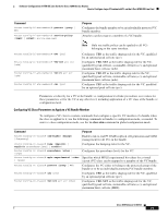
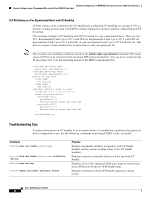
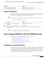
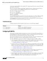
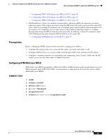
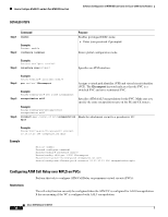
How to Configure AToM VCs on the 4-Port ATM ISE Line Card Software Configuration of ATM ISE Line Cards for Cisco 12000 Series Routers A permanent virtual path (PVP) is like a bundle of VCs, transporting all cells with a common VPI, rather than a specific VPI and VCI. PVCs are created and configured using the pvc command in interface configuration mode. PVPs are created and configured using the atm pvp command in interface configuration mode. The syntax of the pvc command is as follows: pvc [name] vpi/vci l2transport The syntax of the atm pvp command is: atm pvp vpi l2transport vpi is the ATM network VPI to use for this virtual circuit, in the range of 0 to 255 for UNI or 0 to 4095 for NNI; vci is the ATM network VCI to use for this virtual circuit, in the range of 0 to 655,535. The l2transport keyword indicates that the PVP or PVC is a switched PVP/PVC and not terminated. Once you enter this command, you enter l2transport submode. Troubleshooting Tips To display information about the connected virtual circuits, use the following commands: Command Router# show atm pvc Router# show atm vc Purpose Displays current ATM PVC information. Displays current ATM VC information. Configuring AToM VCs Any Transport over MPLS (AToM) encapsulates Layer 2 frames at the ingress PE and sends them to a corresponding PE at the other end of a pseudowire, which is a connection between the two PE routers. The egress PE removes the encapsulation and sends out the Layer 2 frame. The successful transmission of the Layer 2 frames between PE routers is due to the configuration of the PE routers. You set up the connection, called a pseudowire, between the routers. The 4-Port ATM ISE line cards provide a number of configuration options for ATM over MPLS: • AAL5: Encapsulates ATM AAL5 service data units (SDUs) in MPLS packets and forwards them across the MPLS network. Each ATM AAL5 SDU is transported as a single packet. - Configuring ATM AAL5 over MPLS, page 37 • Cell relay in either VC or VP mode: Allows cells coming into a predefined PVC or PVP on the ATM interface to be transported over the MPLS backbone to a predefined PVC or PVP on the egress ATM interface. You can use cell relay mode to send single cells or packed cells over the MPLS backbone. - Configuring ATM Cell Relay over MPLS on PVCs, page 38 - Configuring ATM Cell Relay over MPLS on PVPs, page 40 • Cell relay in port mode: Allows a single cell coming into an ATM interface to be packed into an MPLS packet and transported over the MPLS backbone to an egress ATM interface. - Configuring ATM Cell Relay over MPLS on a Port, page 41 • Packed cell relay in either VP, VC, or port mode: Allows you to insert multiple concatenated ATM cells in an MPLS packet. The packed cell relay feature is more efficient than single cell relay, because each ATM cell is 52 bytes, and each AToM packet is at least 64 bytes. Cisco IOS Release 12.0(27)S 36
-
 1
1 -
2
-
3
-
4
-
5
-
6
-
7
-
8
-
9
-
10
-
11
-
12
-
13
-
14
-
15
-
16
-
17
-
18
-
19
-
20
-
21
-
22
-
23
-
24
-
25
-
26
-
27
-
28
-
29
-
30
-
 31
31 -
 32
32 -
 33
33 -
 34
34 -
 35
35 -
 36
36 -
 37
37 -
 38
38 -
 39
39 -
 40
40 -
 41
41 -
42
-
43
-
44
-
45
-
46
-
47
-
48
-
49
-
50
-
51
-
52
-
53
-
54
-
55
-
56
-
57
-
58
-
59
-
60
-
61
-
62
-
63
-
64
-
65
-
66
-
67
-
68
-
69
-
70
-
71
-
72
-
73
-
74
-
75
-
76
-
77
-
78
-
79
-
80
-
81
-
82
-
83
-
84
-
85
-
86
-
87
-
88
-
89
-
90
-
91
-
92
-
93
-
94
-
95
-
96
-
97
-
98
-
99
-
100
-
101
-
102
 |
 |
