Cisco ISE Software Configuration Guide - Page 8
How to Con Layer 3 Terminated VCs on the 4-Port ATM ISE Line Card - requirements
 |
UPC - 746320730097
View all Cisco ISE manuals
Add to My Manuals
Save this manual to your list of manuals |
Page 8 highlights
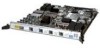
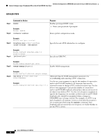
Software Configuration of ATM ISE Line Cards for Cisco 12000 Series Routers How to Configure Layer 3 Terminated VCs on the 4-Port ATM ISE Line Card Command Purpose Router# show atm interface atm slot/port Displays current ATM-specification information about the 4-Port ATM ISE line card interface. Router# show atm traffic Displays current ATM statistics. How to Configure Layer 3 Terminated VCs on the 4-Port ATM ISE Line Card The following configuration tasks are described in this section: • Configuring Layer 3 Terminated Virtual Circuits, page 8 • Configuring ATM Shaping on Terminated VCs, page 9 • Configuring OAM Management on Terminated VCs, page 11 • Configuring Quality of Service on Terminated VCs, page 14 • Configuring and Managing VC Bundles, page 28 • Configuring Bridged PVCs, page 35 Configuring Layer 3 Terminated Virtual Circuits A virtual circuit (VC) is a point-to-point connection between two ATM devices. A VC is established for each ATM end node with which the router communicates. The characteristics of the VC are established when it is created and include the following for the 4-Port ATM ISE line cards: • Quality of service (QoS) • ATM adaptation layer (AAL) mode • Encapsulation type (LLC/SNAP, IP MUX, and NLPID) • Peak and average transmission rates Permanent virtual circuits (PVCs) configured on the router remain active until the circuit is removed from the configuration. All virtual circuit characteristics apply to PVCs. When a PVC is configured, all configuration options are passed to the 4-Port ATM ISE line card. These PVCs are written to the nonvolatile RAM (NVRAM) as part of the configuration and are used when the Cisco IOS image is reloaded. When you create a PVC, you create a virtual circuit descriptor (VCD) and attach it to the VPI and VCI. The VCD tells the card which VPI/VCI to use for a particular packet. The 4-Port ATM ISE line card requires this feature to manage the packets for transmission. The number chosen for the VCD is independent of the VPI/VCI used. A permanent virtual path (PVP) is like a bundle of VCs, transporting all cells with a common VPI, rather than a specific VPI and VCI. PVCs are created and configured using the pvc command in interface configuration mode. PVPs are created and configured using the atm pvp command in interface configuration mode. The syntax of the pvc command is as follows: pvc [name] vpi/vci Cisco IOS Release 12.0(27)S 8
-
 1
1 -
2
-
 3
3 -
 4
4 -
 5
5 -
 6
6 -
 7
7 -
 8
8 -
 9
9 -
 10
10 -
 11
11 -
 12
12 -
 13
13 -
14
-
15
-
16
-
17
-
18
-
19
-
20
-
21
-
22
-
23
-
24
-
25
-
26
-
27
-
28
-
29
-
30
-
31
-
32
-
33
-
34
-
35
-
36
-
37
-
38
-
39
-
40
-
41
-
42
-
43
-
44
-
45
-
46
-
47
-
48
-
49
-
50
-
51
-
52
-
53
-
54
-
55
-
56
-
57
-
58
-
59
-
60
-
61
-
62
-
63
-
64
-
65
-
66
-
67
-
68
-
69
-
70
-
71
-
72
-
73
-
74
-
75
-
76
-
77
-
78
-
79
-
80
-
81
-
82
-
83
-
84
-
85
-
86
-
87
-
88
-
89
-
90
-
91
-
92
-
93
-
94
-
95
-
96
-
97
-
98
-
99
-
100
-
101
-
102
 |
 |
