Cisco ISE Software Configuration Guide - Page 39
Summary Steps, Detailed Steps, Example
 |
UPC - 746320730097
View all Cisco ISE manuals
Add to My Manuals
Save this manual to your list of manuals |
Page 39 highlights
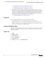
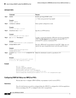
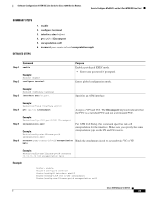
Software Configuration of ATM ISE Line Cards for Cisco 12000 Series Routers How to Configure AToM VCs on the 4-Port ATM ISE Line Card SUMMARY STEPS 1. enable 2. configure terminal 3. interface atmslot/port 4. pvc vpi/vci l2transport 5. encapsulation aal0 6. xconnect peer-router-id vcid encapsulation mpls DETAILED STEPS Step 1 Command enable Step 2 Example: Router> enable configure terminal Purpose Enables privileged EXEC mode. • Enter your password if prompted. Enters global configuration mode. Step 3 Example: Router# configure terminal interface atmslot/port Specifies an ATM interface. Step 4 Step 5 Step 6 Example: Router(config)# interface atm1/0 pvc vpi/vci l2transport Assigns a VPI and VCI. The l2transport keyword indicates that the PVC is a switched PVC and not a terminated PVC. Example: Router(config-if)# pvc 0/100 l2transport encapsulation aal0 Example: Router(config-atm-l2trans-pvc)# encapsulation aal0 xconnect peer-router-id vcid encapsulation mpls For ATM Cell Relay, this command specifies raw cell encapsulation for the interface. Make sure you specify the same encapsulation type on the PE and CE routers. Binds the attachment circuit to a pseudowire VC or VP. Example: Router(config-atm-l2trans-pvc)# xconnect 13.13.13.13 100 encapsulation mpls Example Router> enable Router# configure terminal Router(config)# interface atm1/0 Router(config-if)# pvc 0/100 l2transport Router(config-atm-l2trans-pvc)# encapsulation aal0 Cisco IOS Release 12.0(27)S 39
-
 1
1 -
2
-
3
-
4
-
5
-
6
-
7
-
8
-
9
-
10
-
11
-
12
-
13
-
14
-
15
-
16
-
17
-
18
-
19
-
20
-
21
-
22
-
23
-
24
-
25
-
26
-
27
-
28
-
29
-
30
-
31
-
32
-
33
-
 34
34 -
 35
35 -
 36
36 -
 37
37 -
 38
38 -
 39
39 -
 40
40 -
 41
41 -
 42
42 -
 43
43 -
 44
44 -
45
-
46
-
47
-
48
-
49
-
50
-
51
-
52
-
53
-
54
-
55
-
56
-
57
-
58
-
59
-
60
-
61
-
62
-
63
-
64
-
65
-
66
-
67
-
68
-
69
-
70
-
71
-
72
-
73
-
74
-
75
-
76
-
77
-
78
-
79
-
80
-
81
-
82
-
83
-
84
-
85
-
86
-
87
-
88
-
89
-
90
-
91
-
92
-
93
-
94
-
95
-
96
-
97
-
98
-
99
-
100
-
101
-
102
 |
 |
