Dell PowerEdge MX750c EMC Installation and Service Manual - Page 61
Loosening the screws and set the Anti-Tilt wires to the unlocked position, Steps
 |
View all Dell PowerEdge MX750c manuals
Add to My Manuals
Save this manual to your list of manuals |
Page 61 highlights
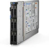
Steps 1. Ensure all four Anti-Tilt wires are in the locked position (outward position), and then using a Torx #T30 screwdriver, loosen the screws on the heat sink in the order that is mentioned below: a. Loosen the first screw three turns. b. Loosen the screw diagonally opposite to the screw you loosened first. c. Repeat the procedure for the remaining two screws. d. Return to the first screw to loosen it completely. 2. Set the Anti-Tilt wires to the unlocked position (inward position). Figure 50. Loosening the screws and set the Anti-Tilt wires to the unlocked position 3. Lift the processor and heat sink module (PHM) from the system and set the PHM aside with the processor side facing up. Installing and removing system components 61
-
 1
1 -
2
-
3
-
4
-
5
-
6
-
7
-
8
-
9
-
10
-
11
-
12
-
13
-
14
-
15
-
16
-
17
-
18
-
19
-
20
-
21
-
22
-
23
-
24
-
25
-
26
-
27
-
28
-
29
-
30
-
31
-
32
-
33
-
34
-
35
-
36
-
37
-
38
-
39
-
40
-
41
-
42
-
43
-
44
-
45
-
46
-
47
-
48
-
49
-
50
-
51
-
52
-
53
-
54
-
55
-
 56
56 -
 57
57 -
 58
58 -
 59
59 -
 60
60 -
 61
61 -
 62
62 -
 63
63 -
 64
64 -
 65
65 -
 66
66 -
67
-
68
-
69
-
70
-
71
-
72
-
73
-
74
-
75
-
76
-
77
-
78
-
79
-
80
-
81
-
82
-
83
-
84
-
85
-
86
-
87
-
88
-
89
-
90
-
91
-
92
-
93
-
94
-
95
-
96
-
97
-
98
-
99
-
100
-
101
-
102
-
103
-
104
-
105
-
106
-
107
-
108
-
109
-
110
-
111
-
112
-
113
 |
 |

Steps
1.
Ensure all four Anti-Tilt wires are in the locked position (outward position), and then using a Torx #T30 screwdriver, loosen
the screws on the heat sink in the order that is mentioned below:
a.
Loosen the first screw three turns.
b.
Loosen the screw diagonally opposite to the screw you loosened first.
c.
Repeat the procedure for the remaining two screws.
d.
Return to the first screw to loosen it completely.
2.
Set the Anti-Tilt wires to the unlocked position (inward position).
Figure 50. Loosening the screws and set the Anti-Tilt wires to the unlocked position
3.
Lift the processor and heat sink module (PHM) from the system and set the PHM aside with the processor side facing up.
Installing and removing system components
61