HP 3500cp Service Manual - Page 313
DesignJet 2500CP/3500CP PostScript SKU, Printed Circuit Assemblies PCA, HPĆGL/2, PJL - mac driver
 |
View all HP 3500cp manuals
Add to My Manuals
Save this manual to your list of manuals |
Page 313 highlights
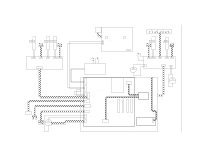
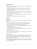
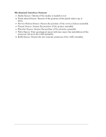
DesignJet 2500CP/3500CP PostScript SKU The PostScript SKU will have a network interface, 20 MB of memory and a Hard Disk Drive. Mac PostScript, Windows PostScript Drivers and HP color kit will be provided. DesignJet 2000CP/3500CP RTL SKU The RTL SKU will have 8 MB of memory. It will not be able to print large/complex HPĆGL/2 or mixed files without extra memory. It will support the HPĆGL/2, PJL, PML and HP RTL languages plus VarWare. No drivers are provided since it is intended for use with an external hardware or software RIP. Printed Circuit Assemblies (PCA) The printer contains a system of several PCA and cabling which link the various sub systems. The PCA system consists of the following: D Power Supply Unit(PSU): This is connected directly to the mains supply. It provides 35v and 26v to the rest of the electrical system. D Main PCA: The controller PCA. It contains the I/O connectors for connection to the host (MAC, PC or network) which provides the data to be printed. The processing of this data is performed by the digital system, the processor, the control ASIC and the memory. The processed data is then sent to the carriage and the printheads via the writing system ASIC, while at the same time the motors and the other systems are controlled by the periphery control ASIC. D Carriage PCA: Connected to the main PCA via the trailing cable. The printhead data and power comes from the main PCA. The Carriage PCA contains two ASICs for driving the four printheads. Also on the carriage PCA are Analogue to Digital Converters (ADCs). These monitor the printheads, the temperature and humidity sensors and the printhead voltages. This information is fed back to the main PCA, enabling control of the printheads over the expected range of environmental conditions. Additionally the YĆaxis encoder signals are sent to the main PCA via the carriage PCA. D Front Panel Assembly: This provides the user interface to the machine. It is connected directly to the main PCA. The front panel assembly consists of the Vacuum Fluorescent Display (VFD), a push button keyboard and light emitting diodes (LEDs). D Service Station Interconnect: This small PCA provides connectivity between the main PCA and the sensors and stepper motors on the right hand side. It is located underneath the service station. Functional Overview HP DesignJet CP Series Printers 10-3
-
 1
1 -
2
-
3
-
4
-
5
-
6
-
7
-
8
-
9
-
10
-
11
-
12
-
13
-
14
-
15
-
16
-
17
-
18
-
19
-
20
-
21
-
22
-
23
-
24
-
25
-
26
-
27
-
28
-
29
-
30
-
31
-
32
-
33
-
34
-
35
-
36
-
37
-
38
-
39
-
40
-
41
-
42
-
43
-
44
-
45
-
46
-
47
-
48
-
49
-
50
-
51
-
52
-
53
-
54
-
55
-
56
-
57
-
58
-
59
-
60
-
61
-
62
-
63
-
64
-
65
-
66
-
67
-
68
-
69
-
70
-
71
-
72
-
73
-
74
-
75
-
76
-
77
-
78
-
79
-
80
-
81
-
82
-
83
-
84
-
85
-
86
-
87
-
88
-
89
-
90
-
91
-
92
-
93
-
94
-
95
-
96
-
97
-
98
-
99
-
100
-
101
-
102
-
103
-
104
-
105
-
106
-
107
-
108
-
109
-
110
-
111
-
112
-
113
-
114
-
115
-
116
-
117
-
118
-
119
-
120
-
121
-
122
-
123
-
124
-
125
-
126
-
127
-
128
-
129
-
130
-
131
-
132
-
133
-
134
-
135
-
136
-
137
-
138
-
139
-
140
-
141
-
142
-
143
-
144
-
145
-
146
-
147
-
148
-
149
-
150
-
151
-
152
-
153
-
154
-
155
-
156
-
157
-
158
-
159
-
160
-
161
-
162
-
163
-
164
-
165
-
166
-
167
-
168
-
169
-
170
-
171
-
172
-
173
-
174
-
175
-
176
-
177
-
178
-
179
-
180
-
181
-
182
-
183
-
184
-
185
-
186
-
187
-
188
-
189
-
190
-
191
-
192
-
193
-
194
-
195
-
196
-
197
-
198
-
199
-
200
-
201
-
202
-
203
-
204
-
205
-
206
-
207
-
208
-
209
-
210
-
211
-
212
-
213
-
214
-
215
-
216
-
217
-
218
-
219
-
220
-
221
-
222
-
223
-
224
-
225
-
226
-
227
-
228
-
229
-
230
-
231
-
232
-
233
-
234
-
235
-
236
-
237
-
238
-
239
-
240
-
241
-
242
-
243
-
244
-
245
-
246
-
247
-
248
-
249
-
250
-
251
-
252
-
253
-
254
-
255
-
256
-
257
-
258
-
259
-
260
-
261
-
262
-
263
-
264
-
265
-
266
-
267
-
268
-
269
-
270
-
271
-
272
-
273
-
274
-
275
-
276
-
277
-
278
-
279
-
280
-
281
-
282
-
283
-
284
-
285
-
286
-
287
-
288
-
289
-
290
-
291
-
292
-
293
-
294
-
295
-
296
-
297
-
298
-
299
-
300
-
301
-
302
-
303
-
304
-
305
-
306
-
307
-
 308
308 -
 309
309 -
 310
310 -
 311
311 -
 312
312 -
 313
313 -
 314
314 -
 315
315 -
 316
316 -
 317
317 -
 318
318 -
319
-
320
-
321
-
322
-
323
-
324
-
325
-
326
-
327
-
328
-
329
-
330
-
331
-
332
 |
 |