HP 4650n HP Color LaserJet 4650 series printer - User Guide - Page 238
The first flash memory slot marked Firmware Slot is reserved for firmware only. Slots 2
 |
UPC - 829160046532
View all HP 4650n manuals
Add to My Manuals
Save this manual to your list of manuals |
Page 238 highlights
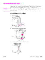
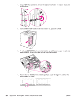
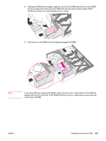
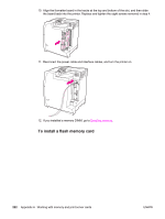
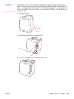
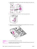
4. Using a #2 Phillips screwdriver, remove the eight screws holding the board in place, and set them aside. 5. Slide out the formatter board and set it on a clean, flat, grounded surface. 6. Align the groove on the side of the flash memory card with the notches in the connector and push it in the slot until it is fully seated. CAUTION Note Do not insert the flash memory card at an angle. The first flash memory slot marked "Firmware Slot" is reserved for firmware only. Slots 2 and 3 should be used for all other solutions. 224 Appendix A Working with memory and print server cards ENWW
-
 1
1 -
2
-
3
-
4
-
5
-
6
-
7
-
8
-
9
-
10
-
11
-
12
-
13
-
14
-
15
-
16
-
17
-
18
-
19
-
20
-
21
-
22
-
23
-
24
-
25
-
26
-
27
-
28
-
29
-
30
-
31
-
32
-
33
-
34
-
35
-
36
-
37
-
38
-
39
-
40
-
41
-
42
-
43
-
44
-
45
-
46
-
47
-
48
-
49
-
50
-
51
-
52
-
53
-
54
-
55
-
56
-
57
-
58
-
59
-
60
-
61
-
62
-
63
-
64
-
65
-
66
-
67
-
68
-
69
-
70
-
71
-
72
-
73
-
74
-
75
-
76
-
77
-
78
-
79
-
80
-
81
-
82
-
83
-
84
-
85
-
86
-
87
-
88
-
89
-
90
-
91
-
92
-
93
-
94
-
95
-
96
-
97
-
98
-
99
-
100
-
101
-
102
-
103
-
104
-
105
-
106
-
107
-
108
-
109
-
110
-
111
-
112
-
113
-
114
-
115
-
116
-
117
-
118
-
119
-
120
-
121
-
122
-
123
-
124
-
125
-
126
-
127
-
128
-
129
-
130
-
131
-
132
-
133
-
134
-
135
-
136
-
137
-
138
-
139
-
140
-
141
-
142
-
143
-
144
-
145
-
146
-
147
-
148
-
149
-
150
-
151
-
152
-
153
-
154
-
155
-
156
-
157
-
158
-
159
-
160
-
161
-
162
-
163
-
164
-
165
-
166
-
167
-
168
-
169
-
170
-
171
-
172
-
173
-
174
-
175
-
176
-
177
-
178
-
179
-
180
-
181
-
182
-
183
-
184
-
185
-
186
-
187
-
188
-
189
-
190
-
191
-
192
-
193
-
194
-
195
-
196
-
197
-
198
-
199
-
200
-
201
-
202
-
203
-
204
-
205
-
206
-
207
-
208
-
209
-
210
-
211
-
212
-
213
-
214
-
215
-
216
-
217
-
218
-
219
-
220
-
221
-
222
-
223
-
224
-
225
-
226
-
227
-
228
-
229
-
230
-
231
-
232
-
 233
233 -
 234
234 -
 235
235 -
 236
236 -
 237
237 -
 238
238 -
 239
239 -
 240
240 -
 241
241 -
 242
242 -
 243
243 -
244
-
245
-
246
-
247
-
248
-
249
-
250
-
251
-
252
-
253
-
254
-
255
-
256
-
257
-
258
-
259
-
260
-
261
-
262
-
263
-
264
-
265
-
266
-
267
-
268
-
269
-
270
-
271
-
272
-
273
-
274
-
275
-
276
 |
 |
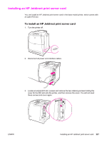
4.
Using a #2 Phillips screwdriver, remove the eight screws holding the board in place, and
set them aside.
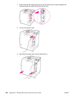
5.
Slide out the formatter board and set it on a clean, flat, grounded surface.
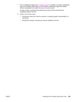
6.
Align the groove on the side of the flash memory card with the notches in the connector
and push it in the slot until it is fully seated.
CAUTION
Do not insert the flash memory card at an angle.
Note
The first flash memory slot marked "Firmware Slot" is reserved for firmware only. Slots 2 and
3 should be used for all other solutions.
224
Appendix A
Working with memory and print server cards
ENWW