HP 6125XLG R2306-HP 6125XLG Blade Switch FCoE Configuration Guide - Page 12
VFC interface and VN interface, FIP protocol, FCoE frames, FCoE network diagram
 |
View all HP 6125XLG manuals
Add to My Manuals
Save this manual to your list of manuals |
Page 12 highlights
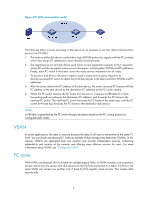
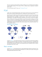
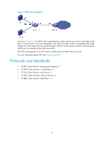
Figure 6 FCoE network diagram VFC interface and VN interface A virtual fiber channel (VFC) interface is a logical interface manually created on the FCF switch to simulate the function of a physical FC interface. To use a VFC interface, bind it to a physical Ethernet interface. You can connect either an ENode or an FCF switch to a VFC interface. VFC interfaces support E mode, F mode (default), and NP mode. The virtual node (VN) interface is a logical interface on an ENode to simulate the function of a physical FC interface. FIP protocol FCoE initialization protocol (FIP) is an FCoE control protocol that establishes and maintains virtual links. FIP establishes a virtual link between the VFC interface of an FCF switch and the VN interface of an ENode or between VFC interfaces of two FCF switches to provide a physical infrastructure for transmitting FC frames over Ethernet. FCoE frames To transmit an FC frame over an Ethernet link, you must encapsulate the FC frame in an FCoE frame by adding an Ethernet frame header to the FC frame. An FCoE frame uses Ethernet II encapsulation, which has the following fields in the Ethernet header: • EtherType 0x8906. • Destination MAC address/source MAC address-For a switch, it is the FCoE MAC address of the switch (which can be displayed by using the display fcoe command). For a node, it is the fabric provided MAC address (FPMA) of the node. As shown in Figure 7, an FPMA is composed of the FC-MAP as the 24 most significant bits and the FC ID of the VN interface as the 24 least significant bits. The FC-MAP takes the value of the switch FC-MAP, 0x0EFC00 by default and configurable by using the fcoe fcmap command. 6
-
 1
1 -
2
-
3
-
4
-
5
-
6
-
 7
7 -
 8
8 -
 9
9 -
 10
10 -
 11
11 -
 12
12 -
 13
13 -
 14
14 -
 15
15 -
 16
16 -
 17
17 -
18
-
19
-
20
-
21
-
22
-
23
-
24
-
25
-
26
-
27
-
28
-
29
-
30
-
31
-
32
-
33
-
34
-
35
-
36
-
37
-
38
-
39
-
40
-
41
-
42
-
43
-
44
-
45
-
46
-
47
-
48
-
49
-
50
-
51
-
52
-
53
-
54
-
55
-
56
-
57
-
58
-
59
-
60
-
61
-
62
-
63
-
64
-
65
-
66
-
67
-
68
-
69
-
70
-
71
-
72
-
73
-
74
-
75
-
76
-
77
-
78
-
79
-
80
-
81
-
82
-
83
-
84
-
85
-
86
-
87
-
88
-
89
-
90
-
91
-
92
-
93
-
94
-
95
-
96
-
97
-
98
-
99
-
100
-
101
-
102
-
103
-
104
-
105
-
106
-
107
-
108
-
109
-
110
-
111
-
112
-
113
-
114
-
115
-
116
-
117
-
118
-
119
-
120
-
121
-
122
-
123
-
124
-
125
-
126
-
127
 |
 |
