HP 6125XLG R2306-HP 6125XLG Blade Switch FCoE Configuration Guide - Page 58
Verifying the configurations, Enable FCoE for VLAN 10 and map VLAN 10 to VSAN 10.
 |
View all HP 6125XLG manuals
Add to My Manuals
Save this manual to your list of manuals |
Page 58 highlights
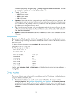
[SwitchA] interface ten-gigabitethernet 1/1/6 [SwitchA-Ten-GigabitEthernet1/1/6] port link-type trunk [SwitchA-Ten-GigabitEthernet1/1/6] port trunk permit vlan 20 [SwitchA-Ten-GigabitEthernet1/1/6] quit # Create interface VFC 4, and configure it to operate in E mode. [SwitchA] interface vfc 4 [SwitchA-Vfc4] fc mode e # Bind interface VFC 4 to interface Ten-GigabitEthernet 1/1/8, and assign it to VSANs 10 and 20 as a trunk port. [SwitchA-Vfc4] bind interface ten-gigabitethernet 1/1/8 [SwitchA-Vfc4] port trunk vsan 10 20 [SwitchA-Vfc4] quit # Assign interface Ten-GigabitEthernet 1/1/8 to VLAN 10 and 20 as a trunk port. [SwitchA] interface ten-gigabitethernet 1/1/8 [SwitchA-Ten-GigabitEthernet1/1/8] port link-type trunk [SwitchA-Ten-GigabitEthernet1/1/8] port trunk permit vlan 10 20 [SwitchA-Ten-GigabitEthernet1/1/8] quit # Enable FCoE for VLAN 10 and map VLAN 10 to VSAN 10. [SwitchA] vlan 10 [SwitchA-vlan10] fcoe enable vsan 10 [SwitchA-vlan10] quit # Enable FCoE for VLAN 20 and map VLAN 20 to VSAN 20. [SwitchA] vlan 20 [SwitchA-vlan20] fcoe enable vsan 20 [SwitchA-vlan20] quit 2. Configure Switch B in the same way Switch A is configured. (Details not shown.) Verifying the configurations 1. Verify the configurations on Switch A by displaying member interfaces of all VSANs. [SwitchA] display vsan port-member VSAN 1: Access Ports: Trunk Ports: VSAN 10: Access Ports: Trunk Ports: Vfc1 Vfc4 VSAN 20: Access Ports: Trunk Ports: Vfc2 Vfc4 2. Verify the configurations on Switch B. 52
-
 1
1 -
2
-
3
-
4
-
5
-
6
-
7
-
8
-
9
-
10
-
11
-
12
-
13
-
14
-
15
-
16
-
17
-
18
-
19
-
20
-
21
-
22
-
23
-
24
-
25
-
26
-
27
-
28
-
29
-
30
-
31
-
32
-
33
-
34
-
35
-
36
-
37
-
38
-
39
-
40
-
41
-
42
-
43
-
44
-
45
-
46
-
47
-
48
-
49
-
50
-
51
-
52
-
 53
53 -
 54
54 -
 55
55 -
 56
56 -
 57
57 -
 58
58 -
 59
59 -
 60
60 -
 61
61 -
 62
62 -
 63
63 -
64
-
65
-
66
-
67
-
68
-
69
-
70
-
71
-
72
-
73
-
74
-
75
-
76
-
77
-
78
-
79
-
80
-
81
-
82
-
83
-
84
-
85
-
86
-
87
-
88
-
89
-
90
-
91
-
92
-
93
-
94
-
95
-
96
-
97
-
98
-
99
-
100
-
101
-
102
-
103
-
104
-
105
-
106
-
107
-
108
-
109
-
110
-
111
-
112
-
113
-
114
-
115
-
116
-
117
-
118
-
119
-
120
-
121
-
122
-
123
-
124
-
125
-
126
-
127
 |
 |
