HP 6125XLG R2306-HP 6125XLG Blade Switch FCoE Configuration Guide - Page 15
FCF mode, NPV mode, VFC interfaces support F mode F_Port and NP mode NP_Port.
 |
View all HP 6125XLG manuals
Add to My Manuals
Save this manual to your list of manuals |
Page 15 highlights
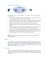
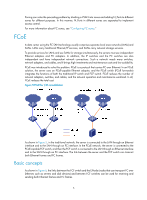
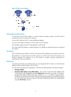
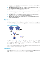
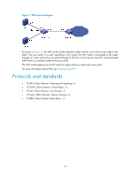
• FCF mode-A switch operating in this mode is called an FCF switch. Its VFC interfaces support E mode (E_Port) and F mode (F_Port). • NPV mode-A switch operating in this mode is called an N_Port Virtualization (NPV) switch. Its VFC interfaces support F mode (F_Port) and NP mode (NP_Port). An FCoE-capable switch can operate in the following modes: • FCF mode-When the switch operates in this mode, it can connect to the E_Port on another FCF switch through its E_Port, or connect to the N_Port on a node or the NP_Port on an NPV switch through its F_Port. • NPV mode-When the switch operates in this mode, it can connect to the N_Port on a node through its F_Port or to the F_Port on an FCF switch through its NP_Port. • Non-FCoE mode-When the switch operates in this mode, it is a standard switch and does not provide any FCoE capabilities. FCF mode An FCF switch encapsulates FC frames in Ethernet frames and uses FCoE virtual links to simulate physical FC links. Therefore, it provides standard FC switching capabilities and features on a lossless Ethernet network. Figure 10 FCF network diagram In an FCoE environment as shown in Figure 10, different from a pure FC network, the ENode and FCF switch communicate over Ethernet interfaces on a lossless Ethernet network. The FCoE virtual link between the ENode and FCF switch connects a VN interface to a VFC interface, and the FCoE virtual link between FCF switches connects two VFC interfaces. Each FCF switch is assigned a domain ID. Each FC SAN supports a maximum number of 239 domain IDs, so an FC SAN cannot have more than 239 FCF switches. NPV mode An FC SAN needs a large number of edge switches that connect directly to nodes. N_Port Virtualization (NPV) switches are developed to expand the number of switches in an FC SAN. 9
-
 1
1 -
2
-
3
-
4
-
5
-
6
-
7
-
8
-
9
-
 10
10 -
 11
11 -
 12
12 -
 13
13 -
 14
14 -
 15
15 -
 16
16 -
 17
17 -
 18
18 -
 19
19 -
 20
20 -
21
-
22
-
23
-
24
-
25
-
26
-
27
-
28
-
29
-
30
-
31
-
32
-
33
-
34
-
35
-
36
-
37
-
38
-
39
-
40
-
41
-
42
-
43
-
44
-
45
-
46
-
47
-
48
-
49
-
50
-
51
-
52
-
53
-
54
-
55
-
56
-
57
-
58
-
59
-
60
-
61
-
62
-
63
-
64
-
65
-
66
-
67
-
68
-
69
-
70
-
71
-
72
-
73
-
74
-
75
-
76
-
77
-
78
-
79
-
80
-
81
-
82
-
83
-
84
-
85
-
86
-
87
-
88
-
89
-
90
-
91
-
92
-
93
-
94
-
95
-
96
-
97
-
98
-
99
-
100
-
101
-
102
-
103
-
104
-
105
-
106
-
107
-
108
-
109
-
110
-
111
-
112
-
113
-
114
-
115
-
116
-
117
-
118
-
119
-
120
-
121
-
122
-
123
-
124
-
125
-
126
-
127
 |
 |
