HP 6125XLG R2306-HP 6125XLG Blade Switch FCoE Configuration Guide - Page 23
VFC interfaces and FIP configuration example, Network requirements, Configuration procedure
 |
View all HP 6125XLG manuals
Add to My Manuals
Save this manual to your list of manuals |
Page 23 highlights
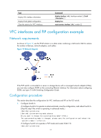
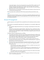
Task Display VFC interface information. Display FCoE global configuration. Clear the statistics for VFC interfaces. Command display interface [ vfc [ interface-number ] ] [ brief [ description ] ] display fcoe reset counters interface [ vfc [ number ] ] VFC interfaces and FIP configuration example Network requirements As shown in Figure 12, use the FCoE solution in a data center combining a LAN and a SAN to reduce the number of devices, network adapters, and cables. Figure 12 Network diagram If the FCF switch is connected to a server or storage device with a converged network adapter (CNA), you must also configure DCBX on the connecting Ethernet interface. For information about configuring DCBX, see Layer 2-LAN Switching Configuration Guide. Configuration procedure This section describes the configurations for VFC interfaces and FIP on the FCF switch. 1. Configure Switch A: # Configure Switch A to operate in advanced mode, save the configuration, and reboot Switch A. (Skip this step if the switch is operating in advanced mode.) system-view [SwitchA] system-working-mode advance Do you want to change the system working mode? [Y/N]:y The system working mode is changed, please save the configuration and reboot the system to make it effective. # Configure Switch A to operate in FCF mode and create VSAN 10. system-view 17
-
 1
1 -
2
-
3
-
4
-
5
-
6
-
7
-
8
-
9
-
10
-
11
-
12
-
13
-
14
-
15
-
16
-
17
-
 18
18 -
 19
19 -
 20
20 -
 21
21 -
 22
22 -
 23
23 -
 24
24 -
 25
25 -
 26
26 -
 27
27 -
 28
28 -
29
-
30
-
31
-
32
-
33
-
34
-
35
-
36
-
37
-
38
-
39
-
40
-
41
-
42
-
43
-
44
-
45
-
46
-
47
-
48
-
49
-
50
-
51
-
52
-
53
-
54
-
55
-
56
-
57
-
58
-
59
-
60
-
61
-
62
-
63
-
64
-
65
-
66
-
67
-
68
-
69
-
70
-
71
-
72
-
73
-
74
-
75
-
76
-
77
-
78
-
79
-
80
-
81
-
82
-
83
-
84
-
85
-
86
-
87
-
88
-
89
-
90
-
91
-
92
-
93
-
94
-
95
-
96
-
97
-
98
-
99
-
100
-
101
-
102
-
103
-
104
-
105
-
106
-
107
-
108
-
109
-
110
-
111
-
112
-
113
-
114
-
115
-
116
-
117
-
118
-
119
-
120
-
121
-
122
-
123
-
124
-
125
-
126
-
127
 |
 |
