HP 6125XLG R2306-HP 6125XLG Blade Switch FCoE Configuration Guide - Page 7
FCoE overview, Storage area network, FC SAN
 |
View all HP 6125XLG manuals
Add to My Manuals
Save this manual to your list of manuals |
Page 7 highlights
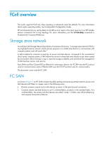
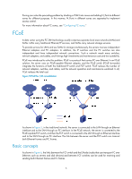
FCoE overview The switch supports FCoE only when operating in advanced mode (the default). For more information about system operating modes, see Fundamentals Configuration Guide. HP recommends that you set the delay for the IRF ports to report a link down event as 0 on IRF member devices connected into a ring topology. For more information, see the irf link-delay command in Fundamentals Command Reference. Storage area network According to the Storage Networking Industry Association dictionary, "a storage area network (SAN) is any high-performance network whose primary purpose is to enable disk devices to communicate with computer systems and with each other." A SAN enables the universal connectivity of servers and disk devices. Compared to the conventional client/server computer system, a SAN allows the servers to share data and directly access data created by one another without having to copy it, improves storage scalability, and centralizes the management of data backup, access, and security. Most SANs use Fibre Channel (FC) or Ethernet to interconnect devices. An FC SAN uses the FC protocol suite for communication, and an Ethernet SAN uses the TCP/IP protocol suite for communication. This document covers only the FC SAN. FC SAN As shown in Figure 1, an FC SAN connects the data sending and receiving entities (network servers and disk devices) with fibers or copper wires in the following ways: • Directly connects a server and a disk device, as shown in the point-to-point connection. • Connects servers and disk devices to an FC switched fabric, as shown in the switched fabric. In a switched fabric, the servers and disk devices are called "nodes." A fabric uses 24-bit addressing and supports thousands of devices. 1
-
 1
1 -
 2
2 -
 3
3 -
 4
4 -
 5
5 -
 6
6 -
 7
7 -
 8
8 -
 9
9 -
 10
10 -
 11
11 -
 12
12 -
13
-
14
-
15
-
16
-
17
-
18
-
19
-
20
-
21
-
22
-
23
-
24
-
25
-
26
-
27
-
28
-
29
-
30
-
31
-
32
-
33
-
34
-
35
-
36
-
37
-
38
-
39
-
40
-
41
-
42
-
43
-
44
-
45
-
46
-
47
-
48
-
49
-
50
-
51
-
52
-
53
-
54
-
55
-
56
-
57
-
58
-
59
-
60
-
61
-
62
-
63
-
64
-
65
-
66
-
67
-
68
-
69
-
70
-
71
-
72
-
73
-
74
-
75
-
76
-
77
-
78
-
79
-
80
-
81
-
82
-
83
-
84
-
85
-
86
-
87
-
88
-
89
-
90
-
91
-
92
-
93
-
94
-
95
-
96
-
97
-
98
-
99
-
100
-
101
-
102
-
103
-
104
-
105
-
106
-
107
-
108
-
109
-
110
-
111
-
112
-
113
-
114
-
115
-
116
-
117
-
118
-
119
-
120
-
121
-
122
-
123
-
124
-
125
-
126
-
127
 |
 |
