HP 6125XLG R2306-HP 6125XLG Blade Switch FCoE Configuration Guide - Page 73
FSPF configuration example, Network requirements, Configuration procedure
 |
View all HP 6125XLG manuals
Add to My Manuals
Save this manual to your list of manuals |
Page 73 highlights
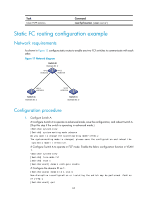
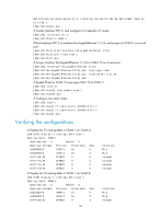
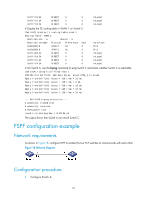
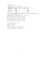
0xfffffa/24 0xfffffc/24 0xfffffd/24 DIRECT 0 DIRECT 0 DIRECT 0 0 InLoop0 0 InLoop0 0 InLoop0 # Display the FC routing table in VSAN 1 on Switch C. [SwitchC] display fc routing-table vsan 1 Routing Table: VSAN 1 Destinations : 6 Routes : 6 Destination/mask Protocol Preference Cost 0x010000/8 STATIC 10 0 0x020000/8 STATIC 10 0 0xfffc03/24 DIRECT 0 0 0xfffffa/24 DIRECT 0 0 0xfffffc/24 DIRECT 0 0 0xfffffd/24 DIRECT 0 0 Interface Vfc2 Vfc2 InLoop0 InLoop0 InLoop0 InLoop0 # On Switch A, use the fcping command to ping Switch C and check whether Switch C is reachable. [SwitchA] fcping fcid fffc03 vsan 1 FCPING fcid 0xfffc03: 128 data bytes, press CTRL_C to break Reply from 0xfffc03: bytes = 128 time = 23 ms Reply from 0xfffc03: bytes = 128 time = 9 ms Reply from 0xfffc03: bytes = 128 time = 19 ms Reply from 0xfffc03: bytes = 128 time = 14 ms Reply from 0xfffc03: bytes = 128 time = 25 ms --- 0xfffc03 fcping statistics --5 packet(s) transmitted 5 packet(s) received 0.00% packet loss round-trip min/avg/max = 9/18/25 ms The output shows that Switch A can reach Switch C. FSPF configuration example Network requirements As shown in Figure 18, configure FSPF to enable the two FCF switches to communicate with each other. Figure 18 Network diagram Configuration procedure 1. Configure Switch A: 67
-
 1
1 -
2
-
3
-
4
-
5
-
6
-
7
-
8
-
9
-
10
-
11
-
12
-
13
-
14
-
15
-
16
-
17
-
18
-
19
-
20
-
21
-
22
-
23
-
24
-
25
-
26
-
27
-
28
-
29
-
30
-
31
-
32
-
33
-
34
-
35
-
36
-
37
-
38
-
39
-
40
-
41
-
42
-
43
-
44
-
45
-
46
-
47
-
48
-
49
-
50
-
51
-
52
-
53
-
54
-
55
-
56
-
57
-
58
-
59
-
60
-
61
-
62
-
63
-
64
-
65
-
66
-
67
-
 68
68 -
 69
69 -
 70
70 -
 71
71 -
 72
72 -
 73
73 -
 74
74 -
 75
75 -
 76
76 -
 77
77 -
 78
78 -
79
-
80
-
81
-
82
-
83
-
84
-
85
-
86
-
87
-
88
-
89
-
90
-
91
-
92
-
93
-
94
-
95
-
96
-
97
-
98
-
99
-
100
-
101
-
102
-
103
-
104
-
105
-
106
-
107
-
108
-
109
-
110
-
111
-
112
-
113
-
114
-
115
-
116
-
117
-
118
-
119
-
120
-
121
-
122
-
123
-
124
-
125
-
126
-
127
 |
 |
