HP 6125XLG R2306-HP 6125XLG Blade Switch FCoE Configuration Guide - Page 44
Configuration procedure, Network diagram
 |
View all HP 6125XLG manuals
Add to My Manuals
Save this manual to your list of manuals |
Page 44 highlights
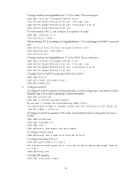
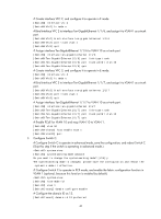
Figure 15 Network diagram Configuration procedure 1. Configure Switch A: # Configure Switch A to operate in advanced mode, save the configuration, and reboot Switch A. (Skip this step if the switch is operating in advanced mode.) system-view [SwitchA] system-working-mode advance Do you want to change the system working mode? [Y/N]:y The system working mode is changed, please save the configuration and reboot the system to make it effective. # Configure Switch A to operate in FCF mode, and enable the fabric configuration function in VSAN 1 (optional, because this function is enabled by default). system-view [SwitchA] fcoe-mode fcf [SwitchA] vsan 1 [SwitchA-vsan1] domain configure enable # Configure the domain ID as 11. [SwitchA-vsan1] domain-id 11 preferred Non-disruptive reconfiguration or isolating the switch may be performed. Continu e? [Y/N]:y [SwitchA-vsan1] quit # Create interface VFC 1, and configure it to operate in E mode. [SwitchA] interface vfc 1 [SwitchA-Vfc1] fc mode e # Bind interface VFC 1 to interface Ten-GigabitEthernet 1/1/5, and assign it to VSAN 1 as a trunk port. [SwitchA-Vfc1] bind interface ten-gigabitethernet 1/1/5 [SwitchA-Vfc1] port trunk vsan 1 [SwitchA-Vfc1] quit # Assign interface Ten-GigabitEthernet 1/1/5 to VLAN 10 as a trunk port. [SwitchA] interface ten-gigabitethernet 1/1/5 [SwitchA-Ten-GigabitEthernet1/1/5] port link-type trunk [SwitchA-Ten-GigabitEthernet1/1/5] port trunk permit vlan 10 [SwitchA-Ten-GigabitEthernet1/1/5] quit # Create interface VFC 2, and configure it to operate in E mode. 38
-
 1
1 -
2
-
3
-
4
-
5
-
6
-
7
-
8
-
9
-
10
-
11
-
12
-
13
-
14
-
15
-
16
-
17
-
18
-
19
-
20
-
21
-
22
-
23
-
24
-
25
-
26
-
27
-
28
-
29
-
30
-
31
-
32
-
33
-
34
-
35
-
36
-
37
-
38
-
 39
39 -
 40
40 -
 41
41 -
 42
42 -
 43
43 -
 44
44 -
 45
45 -
 46
46 -
 47
47 -
 48
48 -
 49
49 -
50
-
51
-
52
-
53
-
54
-
55
-
56
-
57
-
58
-
59
-
60
-
61
-
62
-
63
-
64
-
65
-
66
-
67
-
68
-
69
-
70
-
71
-
72
-
73
-
74
-
75
-
76
-
77
-
78
-
79
-
80
-
81
-
82
-
83
-
84
-
85
-
86
-
87
-
88
-
89
-
90
-
91
-
92
-
93
-
94
-
95
-
96
-
97
-
98
-
99
-
100
-
101
-
102
-
103
-
104
-
105
-
106
-
107
-
108
-
109
-
110
-
111
-
112
-
113
-
114
-
115
-
116
-
117
-
118
-
119
-
120
-
121
-
122
-
123
-
124
-
125
-
126
-
127
 |
 |
