Honeywell HJC4000 User Guide - Page 7

Honeywell HJC4000 Manual

Page 7 highlights

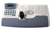
UltraKey Touch Installation and User Guide Figures Figure 1-1 Figure 1-2 Figure 2-1 Figure 2-2 Figure 3-1 Figure 3-2 Figure 3-3 Figure 3-4 Figure 3-5 Figure 3-6 Figure 3-7 Figure 3-8 Figure 3-9 Figure 3-10 Figure 4-1 Figure 4-2 Figure 4-3 Figure 4-4 Figure 4-5 Figure 4-6 Figure 5-1 Figure 5-2 Figure A-1 UltraKey Touch Port Connections 18 RJ45 Box Front and Back Ports 19 UltraKey Touch Controller Keyboard Layout 22 UltraKey Touch Navigation Controls 24 LCD and LCD Navigation Keys 26 DVR Configuration Menu Tree 26 Connecting the Controller for DVR Control 28 Connecting the Controller for DVR Control Using RS485 32 Ethernet Port Connections to DVR 36 UltraKey Touch Login Page 39 System Configuration Tab 40 Standalone Configuration for DVR Tab 41 Serial Port Configuration Tab 42 IP Configuration Tab 43 PTZ Configuration Menu Tree 52 RS485 Serial Port Connection PTZ by RJ45 Box 53 UltraKey Touch Login page 56 System Configuration Tab 57 Standalone Configuration for PTZ Tab 58 Serial Port Configuration Tab 59 Software Upgrade Warning Message 68 Change Password Page 69 System Configuration LCD Menu Tree - All Modes 75 Document 800-06554 Rev C 7 11/10

  • 1
  • 2
  • 3
  • 4
  • 5
  • 6
  • 7
  • 8
  • 9
  • 10
  • 11
  • 12
  • 13
  • 14
  • 15
  • 16
  • 17
  • 18
  • 19
  • 20
  • 21
  • 22
  • 23
  • 24
  • 25
  • 26
  • 27
  • 28
  • 29
  • 30
  • 31
  • 32
  • 33
  • 34
  • 35
  • 36
  • 37
  • 38
  • 39
  • 40
  • 41
  • 42
  • 43
  • 44
  • 45
  • 46
  • 47
  • 48
  • 49
  • 50
  • 51
  • 52
  • 53
  • 54
  • 55
  • 56
  • 57
  • 58
  • 59
  • 60
  • 61
  • 62
  • 63
  • 64
  • 65
  • 66
  • 67
  • 68
  • 69
  • 70
  • 71
  • 72
  • 73
  • 74
  • 75
  • 76
  • 77
  • 78

UltraKey Touch Installation and User Guide
Document 800-06554 Rev C
7
11/10
Figures
Figure 1-1
UltraKey Touch Port Connections .
.
.
.
.
.
.
.
.
.
.
.
.
.
.
.
.
.
.
.
.
.
.
.
.
.
.
.
. .
. 18
Figure 1-2
RJ45 Box Front and Back Ports .
.
.
.
.
.
.
.
.
.
.
.
.
.
.
.
.
.
.
.
.
.
.
.
.
.
.
.
.
.
.
. 19
Figure 2-1
UltraKey Touch Controller Keyboard Layout
.
.
.
.
.
.
.
.
.
.
.
.
.
.
.
.
.
.
.
.
.
.
.
.
. 22
Figure 2-2
UltraKey Touch Navigation Controls
.
.
.
.
.
.
.
.
.
.
.
.
.
.
.
.
.
.
.
.
.
.
.
.
.
.
.
.
. 24
Figure 3-1
LCD and LCD Navigation Keys
.
.
.
.
.
.
.
.
.
.
.
.
.
.
.
.
.
.
.
.
.
.
.
.
.
.
.
.
.
.
.
. 26
Figure 3-2
DVR Configuration Menu Tree.
.
.
.
.
.
.
.
.
.
.
.
.
.
.
.
.
.
.
.
.
.
.
.
.
.
.
.
.
.
.
.
. 26
Figure 3-3
Connecting the Controller for DVR Control .
.
.
.
.
.
.
.
.
.
.
.
.
.
.
.
.
.
.
.
.
.
.
.
.
. 28
Figure 3-4
Connecting the Controller for DVR Control Using RS485.
.
.
.
.
.
.
.
.
.
.
.
.
.
.
.
.
.
. 32
Figure 3-5
Ethernet Port Connections to DVR
.
.
.
.
.
.
.
.
.
.
.
.
.
.
.
.
.
.
.
.
.
.
.
.
.
.
.
. .
. 36
Figure 3-6
UltraKey Touch Login Page .
.
.
.
.
.
.
.
.
.
.
.
.
.
.
.
.
.
.
.
.
.
.
.
.
.
.
.
.
.
.
.
.
. 39
Figure 3-7
System Configuration Tab .
.
.
.
.
.
.
.
.
.
.
.
.
.
.
.
.
.
.
.
.
.
.
.
.
.
.
.
.
.
.
.
.
.
. 40
Figure 3-8
Standalone Configuration for DVR Tab .
.
.
.
.
.
.
.
.
.
.
.
.
.
.
.
.
.
.
.
.
.
.
.
.
.
. . 41
Figure 3-9
Serial Port Configuration Tab .
.
.
.
.
.
.
.
.
.
.
.
.
.
.
.
.
.
.
.
.
.
.
.
.
.
.
.
.
.
.
.
. 42
Figure 3-10
IP Configuration Tab
.
.
.
.
.
.
.
.
.
.
.
.
.
.
.
.
.
.
.
.
.
.
.
.
.
.
.
.
.
.
.
.
.
.
.
.
. 43
Figure 4-1
PTZ Configuration Menu Tree .
.
.
.
.
.
.
.
.
.
.
.
.
.
.
.
.
.
.
.
.
.
.
.
.
.
.
.
.
.
.
.
. 52
Figure 4-2
RS485 Serial Port Connection PTZ by RJ45 Box .
.
.
.
.
.
.
.
.
.
.
.
.
.
.
.
.
.
.
.
.
.
. 53
Figure 4-3
UltraKey Touch Login page .
.
.
.
.
.
.
.
.
.
.
.
.
.
.
.
.
.
.
.
.
.
.
.
.
.
.
.
.
.
.
.
.
. 56
Figure 4-4
System Configuration Tab .
.
.
.
.
.
.
.
.
.
.
.
.
.
.
.
.
.
.
.
.
.
.
.
.
.
.
.
.
.
.
.
.
.
. 57
Figure 4-5
Standalone Configuration for PTZ Tab
.
.
.
.
.
.
.
.
.
.
.
.
.
.
.
.
.
.
.
.
.
.
.
.
.
.
.
. 58
Figure 4-6
Serial Port Configuration Tab .
.
.
.
.
.
.
.
.
.
.
.
.
.
.
.
.
.
.
.
.
.
.
.
.
.
.
.
.
.
.
.
. 59
Figure 5-1
Software Upgrade Warning Message .
.
.
.
.
.
.
.
. .
.
.
.
.
.
.
.
.
.
.
.
.
.
.
.
.
.
.
. 68
Figure 5-2
Change Password Page .
.
.
.
.
.
.
.
.
.
.
.
.
.
.
.
.
.
.
.
.
.
.
.
.
.
.
.
.
.
.
.
.
.
.
. 69
Figure A-1
System Configuration LCD Menu Tree - All Modes .
.
.
.
.
.
.
.
.
.
.
.
.
.
.
.
.
.
.
.
.
. 75