IBM x3400 Installation Guide - Page 29
Removing, front, assembly
 |
View all IBM x3400 manuals
Add to My Manuals
Save this manual to your list of manuals |
Page 29 highlights
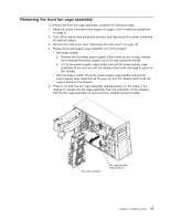
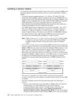
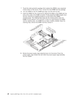
Removing the front fan cage assembly To remove the front fan cage assembly, complete the following steps: 1. Read the safety information that begins on page v and "Installation guidelines" on page 9. 2. Turn off the server and peripheral devices, and disconnect the power cords and all external cables. 3. Remove the side cover (see "Removing the side cover" on page 12). 4. Rotate the power-supply cage assembly out of the chassis: v Hot-swap models: a. Remove the hot-swap power-supply. Press down on the orange release lever and pull the power supply out of the bay, using the handle. b. Lift up the power-supply cage handle and pull the power-supply cage assembly all the way up until the retainer latch locks the cage in place on the chassis. v Non-hot-swap models, lift up the power-supply cage handle and pull the power-supply cage assembly all the way up until the retainer latch locks the cage in place on the chassis. 5. Press in on both the fan cage assembly release buttons on the sides of the chassis to release the fan cage assembly from the connector on the chassis. Pull the fan cage assembly up and out of the chassis and set it aside. Fan cage assembly Fan cage assembly release buttons Chapter 2. Installing options 15
-
 1
1 -
2
-
3
-
4
-
5
-
6
-
7
-
8
-
9
-
10
-
11
-
12
-
13
-
14
-
15
-
16
-
17
-
18
-
19
-
20
-
21
-
22
-
23
-
 24
24 -
 25
25 -
 26
26 -
 27
27 -
 28
28 -
 29
29 -
 30
30 -
 31
31 -
 32
32 -
 33
33 -
 34
34 -
35
-
36
-
37
-
38
-
39
-
40
-
41
-
42
-
43
-
44
-
45
-
46
-
47
-
48
-
49
-
50
-
51
-
52
-
53
-
54
-
55
-
56
-
57
-
58
-
59
-
60
-
61
-
62
-
63
-
64
-
65
-
66
-
67
-
68
-
69
-
70
-
71
-
72
-
73
-
74
-
75
-
76
-
77
-
78
-
79
-
80
-
81
-
82
-
83
-
84
-
85
-
86
-
87
-
88
-
89
-
90
-
91
-
92
-
93
-
94
-
95
-
96
-
97
-
98
-
99
-
100
-
101
-
102
-
103
-
104
-
105
-
106
-
107
-
108
-
109
-
110
-
111
-
112
-
113
-
114
-
115
-
116
-
117
-
118
-
119
-
120
-
121
-
122
-
123
-
124
 |
 |