IBM x3400 Installation Guide - Page 40
simple-swap-drive
 |
View all IBM x3400 manuals
Add to My Manuals
Save this manual to your list of manuals |
Page 40 highlights
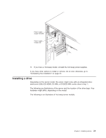
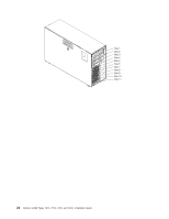
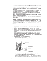
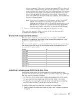
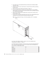
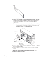
2. Turn off the server and peripheral devices and disconnect all external cables and power cords. 3. Unlock the side cover (you cannot open or remove the bezel without unlocking the side cover). 4. Remove the bezel (see "Removing the bezel" on page 13. 5. Touch the static-protective package that contains the drive to any unpainted metal surface on the server; then, remove the drive from the package and place it on a static-protective surface. 6. Align the drive assembly with the guide rails in the bay (the connector end of the drive goes in first). 7. Press the drive assembly loops toward each other; then, carefully slide the drive assembly into the drive bay until it stops and release the loops. Note: Do not release the loops on the drive assembly until it is completely seated. If you have other options to install or remove, do so now; otherwise, go to "Completing the installation" on page 31. The simple-swap-drive backplate controls the IDs for the internal simple-swap drive bays. The following table lists the IDs for the hard disk drives and backplate that are connected to simple-swap models. Device ID Drive bay 4 3 Drive bay 5 2 Drive bay 6 1 Drive bay 7 0 26 System x3400 Types 7973, 7974, 7975, and 7976: Installation Guide
-
 1
1 -
2
-
3
-
4
-
5
-
6
-
7
-
8
-
9
-
10
-
11
-
12
-
13
-
14
-
15
-
16
-
17
-
18
-
19
-
20
-
21
-
22
-
23
-
24
-
25
-
26
-
27
-
28
-
29
-
30
-
31
-
32
-
33
-
34
-
 35
35 -
 36
36 -
 37
37 -
 38
38 -
 39
39 -
 40
40 -
 41
41 -
 42
42 -
 43
43 -
 44
44 -
 45
45 -
46
-
47
-
48
-
49
-
50
-
51
-
52
-
53
-
54
-
55
-
56
-
57
-
58
-
59
-
60
-
61
-
62
-
63
-
64
-
65
-
66
-
67
-
68
-
69
-
70
-
71
-
72
-
73
-
74
-
75
-
76
-
77
-
78
-
79
-
80
-
81
-
82
-
83
-
84
-
85
-
86
-
87
-
88
-
89
-
90
-
91
-
92
-
93
-
94
-
95
-
96
-
97
-
98
-
99
-
100
-
101
-
102
-
103
-
104
-
105
-
106
-
107
-
108
-
109
-
110
-
111
-
112
-
113
-
114
-
115
-
116
-
117
-
118
-
119
-
120
-
121
-
122
-
123
-
124
 |
 |
