IBM x3400 Installation Guide - Page 34
simultaneously.
 |
View all IBM x3400 manuals
Add to My Manuals
Save this manual to your list of manuals |
Page 34 highlights
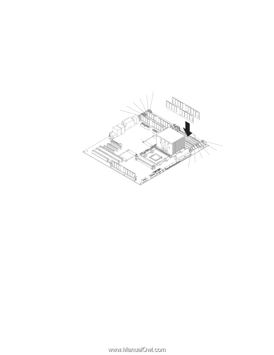
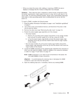
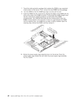
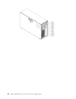
7. Touch the static-protective package that contains the DIMM to any unpainted metal surface on the server. Then, remove the new DIMM from the package. 8. Turn the DIMM so that the DIMM keys align correctly with the slot. 9. Insert the DIMM into the connector by aligning the edges of the DIMM with the slots at the ends of the DIMM connector. Firmly press the DIMM straight down into the connector by applying pressure on both ends of the DIMM simultaneously. The retaining clips snap into the locked position when the DIMM is firmly seated in the connector. If there is a gap between the DIMM and the retaining clips, the DIMM has not been correctly installed. Open the retaining clips, remove the DIMM, and then reinsert it. DIMM 6 DIMM 5 DIMM4 DIMM3 DIMM 2 DIMM 1 DIMM 12 DIMM11 DIMM 10 DIMM 9 DIMM 8 DIMM 7 10. Rotate the power-supply cage assembly back into the server. Press the power-supply cage release tab and rotate the power-supply cage assembly into the chassis. 20 System x3400 Types 7973, 7974, 7975, and 7976: Installation Guide
-
 1
1 -
2
-
3
-
4
-
5
-
6
-
7
-
8
-
9
-
10
-
11
-
12
-
13
-
14
-
15
-
16
-
17
-
18
-
19
-
20
-
21
-
22
-
23
-
24
-
25
-
26
-
27
-
28
-
 29
29 -
 30
30 -
 31
31 -
 32
32 -
 33
33 -
 34
34 -
 35
35 -
 36
36 -
 37
37 -
 38
38 -
 39
39 -
40
-
41
-
42
-
43
-
44
-
45
-
46
-
47
-
48
-
49
-
50
-
51
-
52
-
53
-
54
-
55
-
56
-
57
-
58
-
59
-
60
-
61
-
62
-
63
-
64
-
65
-
66
-
67
-
68
-
69
-
70
-
71
-
72
-
73
-
74
-
75
-
76
-
77
-
78
-
79
-
80
-
81
-
82
-
83
-
84
-
85
-
86
-
87
-
88
-
89
-
90
-
91
-
92
-
93
-
94
-
95
-
96
-
97
-
98
-
99
-
100
-
101
-
102
-
103
-
104
-
105
-
106
-
107
-
108
-
109
-
110
-
111
-
112
-
113
-
114
-
115
-
116
-
117
-
118
-
119
-
120
-
121
-
122
-
123
-
124
 |
 |