IBM x3400 Installation Guide - Page 43
Start, Options - bios
 |
View all IBM x3400 manuals
Add to My Manuals
Save this manual to your list of manuals |
Page 43 highlights
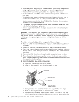
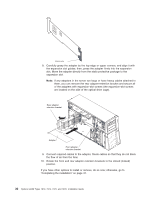
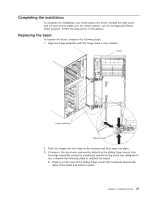
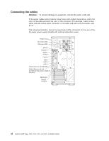
ServeRAID-MR10is SAS/SATA controller. For instructions on how to install the ServeRAID-MR10is SAS/SATA controller, see the User's Guide. Note: Note: The onboard RAID controller will be disabled by BIOS when the ServeRAID-MR10is SAS/SATA controller is installed in the server. v v The server scans the onboard SAS/SATA controller, PCI Express slot 1, PCI-X slots 4 and 5, PCI-Express slots 2 and 3, onboard Ethernet controllers, and PCI slot 6 to assign system resources. Then, the server starts the devices in the following order, if you have not changed the default startup sequence: PCI Express slot 1, PCI-X slots 4 and 5, PCI Express slot 2, PCI slot 6, and PCI Express slot 3. Note: You can change the sequence in which the server start (boot) the devices using the Start Options menu choice from the Configuration/Setup Utility program main menu. See the User's Guide for detailed information about using the Configuration/Setup Utility program. v For a list of supported options for the server, see http://www.ibm.com/servers/ eserver/serverproven/compat/us/. To install an adapter, complete the following steps: 1. Read the safety information that begins on page v and "Installation guidelines" on page 9. 2. Turn off the server and peripheral devices and disconnect all external cables and power cords; then, remove the side cover. See "Removing the side cover" on page 12. 3. Follow the cabling instructions that come with the adapter to set jumpers or switches, if there are any. Route the adapter cables before you install the adapter. 4. Rotate the front and rear adapter-retention brackets to the open (unlocked) position. 5. Remove the screw that secures the expansion-slot cover to the chassis. Store the expansion-slot cover and screw in a safe place for future use. Note: Expansion-slot covers must be installed on all vacant slots. This maintains the electronic emissions standards of the server and ensures proper ventilation of server components. 6. Touch the static-protective package that contains the adapter to any unpainted metal surface on the server. Then, remove the adapter from the static-protective package. Avoid touching the components and gold-edge connectors on the adapter. 7. If you are installing a full-length adapter, remove the blue adapter guide (if any) from the end of the adapter; then, lift the adapter-retention clip on the adapter-support bracket. Chapter 2. Installing options 29
-
 1
1 -
2
-
3
-
4
-
5
-
6
-
7
-
8
-
9
-
10
-
11
-
12
-
13
-
14
-
15
-
16
-
17
-
18
-
19
-
20
-
21
-
22
-
23
-
24
-
25
-
26
-
27
-
28
-
29
-
30
-
31
-
32
-
33
-
34
-
35
-
36
-
37
-
 38
38 -
 39
39 -
 40
40 -
 41
41 -
 42
42 -
 43
43 -
 44
44 -
 45
45 -
 46
46 -
 47
47 -
 48
48 -
49
-
50
-
51
-
52
-
53
-
54
-
55
-
56
-
57
-
58
-
59
-
60
-
61
-
62
-
63
-
64
-
65
-
66
-
67
-
68
-
69
-
70
-
71
-
72
-
73
-
74
-
75
-
76
-
77
-
78
-
79
-
80
-
81
-
82
-
83
-
84
-
85
-
86
-
87
-
88
-
89
-
90
-
91
-
92
-
93
-
94
-
95
-
96
-
97
-
98
-
99
-
100
-
101
-
102
-
103
-
104
-
105
-
106
-
107
-
108
-
109
-
110
-
111
-
112
-
113
-
114
-
115
-
116
-
117
-
118
-
119
-
120
-
121
-
122
-
123
-
124
 |
 |