IBM x3400 Installation Guide - Page 33
Attention
 |
View all IBM x3400 manuals
Add to My Manuals
Save this manual to your list of manuals |
Page 33 highlights
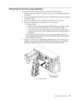
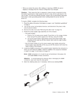
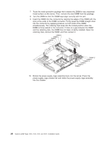
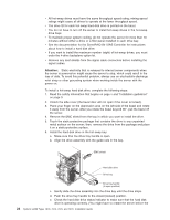
v When you restart the server after adding or removing a DIMM, the server displays a message that the memory configuration has changed. Attention: Static electricity that is released to internal server components when the server is powered-on might cause the server to stop, which could result in the loss of data. To avoid this potential problem, always use an electrostatic-discharge wrist strap or other grounding system when working inside the server with the power on. To install a DIMM, complete the following steps: 1. Read the safety information that begins on page v and "Installation guidelines" on page 9. 2. Turn off the server and peripheral devices, and disconnect the power cords and all external cables. 3. Remove the side cover (see "Removing the side cover" on page 12). 4. Rotate the power-supply cage assembly out of the chassis: v Hot-swap models: a. Remove the hot-swap power-supply. Press down on the orange release lever and pull the power supply out of the bay, using the handle. b. Lift up the power-supply cage handle and pull the power-supply cage assembly all the way up until the retainer latch locks the cage in place on the chassis. v Non-hot-swap models, lift up the power-supply cage handle and pull the power-supply cage assembly all the way up until the retainer latch locks the cage in place on the chassis. 5. Locate the DIMM connectors on the system board. Determine the connector in which you will install the DIMMs. Install the DIMMs in the sequence indicated in Table 3 on page 17 and Table 4 on page 18 Note: DIMM connectors 3, 6, 9, and 12 are not functional in this server. Do not install DIMMs in these connectors. Attention: To avoid breaking the retaining clips or damaging the DIMM connectors, open and close the clips gently. 6. Open the retaining clips and, if necessary, remove any existing DIMM. Chapter 2. Installing options 19
-
 1
1 -
2
-
3
-
4
-
5
-
6
-
7
-
8
-
9
-
10
-
11
-
12
-
13
-
14
-
15
-
16
-
17
-
18
-
19
-
20
-
21
-
22
-
23
-
24
-
25
-
26
-
27
-
 28
28 -
 29
29 -
 30
30 -
 31
31 -
 32
32 -
 33
33 -
 34
34 -
 35
35 -
 36
36 -
 37
37 -
 38
38 -
39
-
40
-
41
-
42
-
43
-
44
-
45
-
46
-
47
-
48
-
49
-
50
-
51
-
52
-
53
-
54
-
55
-
56
-
57
-
58
-
59
-
60
-
61
-
62
-
63
-
64
-
65
-
66
-
67
-
68
-
69
-
70
-
71
-
72
-
73
-
74
-
75
-
76
-
77
-
78
-
79
-
80
-
81
-
82
-
83
-
84
-
85
-
86
-
87
-
88
-
89
-
90
-
91
-
92
-
93
-
94
-
95
-
96
-
97
-
98
-
99
-
100
-
101
-
102
-
103
-
104
-
105
-
106
-
107
-
108
-
109
-
110
-
111
-
112
-
113
-
114
-
115
-
116
-
117
-
118
-
119
-
120
-
121
-
122
-
123
-
124
 |
 |