IBM x3400 Installation Guide - Page 41
Power, signal, cables, internal, drives - review
 |
View all IBM x3400 manuals
Add to My Manuals
Save this manual to your list of manuals |
Page 41 highlights
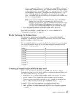
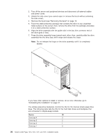
Power and signal cables for internal drives The server uses cables to connect parallel IDE, simple-swap SATA, hot-swap SATA and hot-swap SAS devices to the power supply and to the system board. (See the User's Guide for the location of system-board connectors.) Review the following information before connecting power and signal cables to internal drives: v The drives that are preinstalled in the server come with power and signal cables attached. If you replace any drives, remember which cable is attached to which drive. v If you have only one IDE device on a cable, it must be set as a master device. v If two IDE devices are used on a single cable, one must be designated as the master device and the other as the subordinate device; otherwise, the server might not recognize some of the IDE devices. The master and subordinate designation is determined by switch or jumper settings on each IDE device. v When you route a cable, make sure that it does not block the airflow to the rear of the drives or over the microprocessor or DIMMs. The following cables are provided: v IDE: The wider IDE signal cable has three connectors. One of these connectors is attached to the drive, one is a spare, and the third is attached to the IDE connector on the system board. The spare connector can be used to connect an additional IDE optical drive or tape drive to the server. The CD or DVD drive is attached to an ATA 100 signal cable. The blue connector is attached to the system board. The connector on the other end is attached to the master IDE device. The middle connector attaches to an optional optical device or tape drive. v Simple-swap SATA: The combination signal/power cable connects to the system board and simple-swap backplate to provide signal and power to the simple-swap SATA drives. Simple-swap SATA models come with one of the combination signal/power cable connected to the system board and the simple-swap SATA backplate. Notes: 1. You can install the optional ServeRAID-8k Controller in the simple-swap SATA models to get RAID level-5 support. If you install the ServeRAID-8k Controller, you will need to switch the hard disk drive signal cable to a different connector on the system board and connect a RAID level-5 Enabler plug to the system board. See the User's Guide for information on how to install and cable ServeRAID-8k Controller in simple-swap SATA models for RAID level-5 support. 2. When you install the optional ServeRAID-8k Controller in the simple-swap SATA models for RAID support, make sure that you remove the dust shield (if one is present) from the signal connector on the system board before installing the signal cable. Carefully grasp the dust shield and pull it out of the signal connector. v You can order an optional IBM ServeRAID-MR10is VAULT SAS/SATA Controller that supports RAID levels 0, 1, 5, 6, 10, 50, and 60. You can install the ServeRAID-MR10is SAS/SATA controller only in server models with eight 3.5 inch hot-swap hard disk drives installed. For instructions on how to install the ServeRAID-MR10is SAS/SATA controller, see the User's Guide. Note: Note: The onboard RAID controller will be disabled by BIOS when the ServeRAID-MR10is SAS/SATA controller is installed in the server. Chapter 2. Installing options 27
-
 1
1 -
2
-
3
-
4
-
5
-
6
-
7
-
8
-
9
-
10
-
11
-
12
-
13
-
14
-
15
-
16
-
17
-
18
-
19
-
20
-
21
-
22
-
23
-
24
-
25
-
26
-
27
-
28
-
29
-
30
-
31
-
32
-
33
-
34
-
35
-
 36
36 -
 37
37 -
 38
38 -
 39
39 -
 40
40 -
 41
41 -
 42
42 -
 43
43 -
 44
44 -
 45
45 -
 46
46 -
47
-
48
-
49
-
50
-
51
-
52
-
53
-
54
-
55
-
56
-
57
-
58
-
59
-
60
-
61
-
62
-
63
-
64
-
65
-
66
-
67
-
68
-
69
-
70
-
71
-
72
-
73
-
74
-
75
-
76
-
77
-
78
-
79
-
80
-
81
-
82
-
83
-
84
-
85
-
86
-
87
-
88
-
89
-
90
-
91
-
92
-
93
-
94
-
95
-
96
-
97
-
98
-
99
-
100
-
101
-
102
-
103
-
104
-
105
-
106
-
107
-
108
-
109
-
110
-
111
-
112
-
113
-
114
-
115
-
116
-
117
-
118
-
119
-
120
-
121
-
122
-
123
-
124
 |
 |