Lenovo ThinkCentre M70z Hardware Maintenance Manual (HMM) - Page 112
Replacing the system board
 |
View all Lenovo ThinkCentre M70z manuals
Add to My Manuals
Save this manual to your list of manuals |
Page 112 highlights
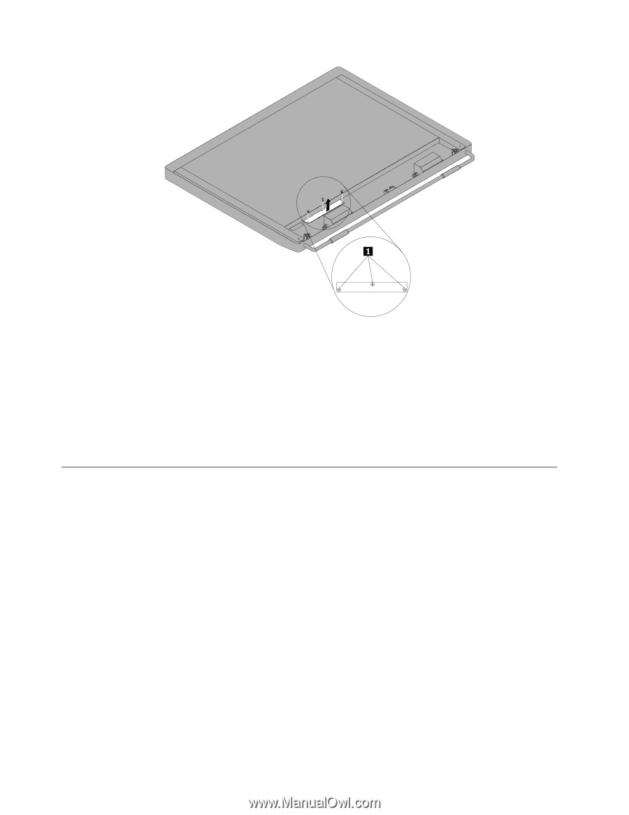
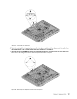
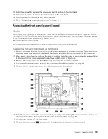
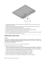
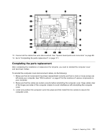
9. Disconnect the front panel control board cable from the system board. Lift the front panel control board off the front bezel. 10. Position the new front panel control board on the front bezel and align the screw holes in the new power switch module with those in the front bezel. 11. Connect the new front panel control board cable to the system board. 12. Install the three screws that secure the new front panel control board to the front bezel. 13. Install the 21 screws to secure the main bracket to the front bezel. 14. Connect all the cables that were disconnected. See "System board parts and connectors" on page 69. 15. Go to "Completing the parts replacement" on page 111. Replacing the system board Attention Do not open your computer or attempt any repair before reading and understanding the "Important safety information" in the ThinkCentre Safety and Warranty Guide that came with your computer. To obtain a copy of the ThinkCentre Safety and Warranty Guide, go to: http://www.lenovo.com/support This section provides instructions on how to replace the system board. To replace the power system board, do the following: 1. Remove all media from the drives and turn off all attached devices and the computer. Then, disconnect all power cords from electrical outlets and disconnect all cables that are connected to the computer. 2. Place a soft, clean towel or cloth on the desk or surface. Hold the sides of your computer and gently lay it down so that the screen is against the surface and the cover is facing up. 3. Remove the computer cover. See "Removing the computer cover" on page 71. 4. Locate the system board in the computer. See "FRU locations" on page 67. 5. Remove the hard disk drive. See "Replacing the hard disk drive" on page 72. 6. Remove the wall mount. See "Removing or reinstalling the wall mount" on page 80. 106 ThinkCentre Hardware Maintenance Manual
-
 1
1 -
2
-
3
-
4
-
5
-
6
-
7
-
8
-
9
-
10
-
11
-
12
-
13
-
14
-
15
-
16
-
17
-
18
-
19
-
20
-
21
-
22
-
23
-
24
-
25
-
26
-
27
-
28
-
29
-
30
-
31
-
32
-
33
-
34
-
35
-
36
-
37
-
38
-
39
-
40
-
41
-
42
-
43
-
44
-
45
-
46
-
47
-
48
-
49
-
50
-
51
-
52
-
53
-
54
-
55
-
56
-
57
-
58
-
59
-
60
-
61
-
62
-
63
-
64
-
65
-
66
-
67
-
68
-
69
-
70
-
71
-
72
-
73
-
74
-
75
-
76
-
77
-
78
-
79
-
80
-
81
-
82
-
83
-
84
-
85
-
86
-
87
-
88
-
89
-
90
-
91
-
92
-
93
-
94
-
95
-
96
-
97
-
98
-
99
-
100
-
101
-
102
-
103
-
104
-
105
-
106
-
 107
107 -
 108
108 -
 109
109 -
 110
110 -
 111
111 -
 112
112 -
 113
113 -
 114
114 -
 115
115 -
 116
116 -
 117
117 -
118
-
119
-
120
-
121
-
122
-
123
-
124
-
125
-
126
-
127
-
128
-
129
-
130
-
131
-
132
-
133
-
134
-
135
-
136
-
137
-
138
-
139
-
140
-
141
-
142
-
143
-
144
-
145
-
146
-
147
-
148
-
149
-
150
-
151
-
152
-
153
-
154
-
155
-
156
-
157
-
158
-
159
-
160
-
161
-
162
-
163
-
164
-
165
-
166
-
167
-
168
-
169
-
170
-
171
-
172
-
173
-
174
-
175
-
176
-
177
-
178
-
179
-
180
-
181
-
182
-
183
-
184
-
185
-
186
-
187
-
188
-
189
-
190
-
191
-
192
-
193
-
194
-
195
-
196
-
197
-
198
-
199
-
200
-
201
-
202
-
203
-
204
-
205
-
206
-
207
-
208
 |
 |