Lenovo ThinkCentre M70z Hardware Maintenance Manual (HMM) - Page 93
Replacing the microprocessor, Notes, Attention
 |
View all Lenovo ThinkCentre M70z manuals
Add to My Manuals
Save this manual to your list of manuals |
Page 93 highlights
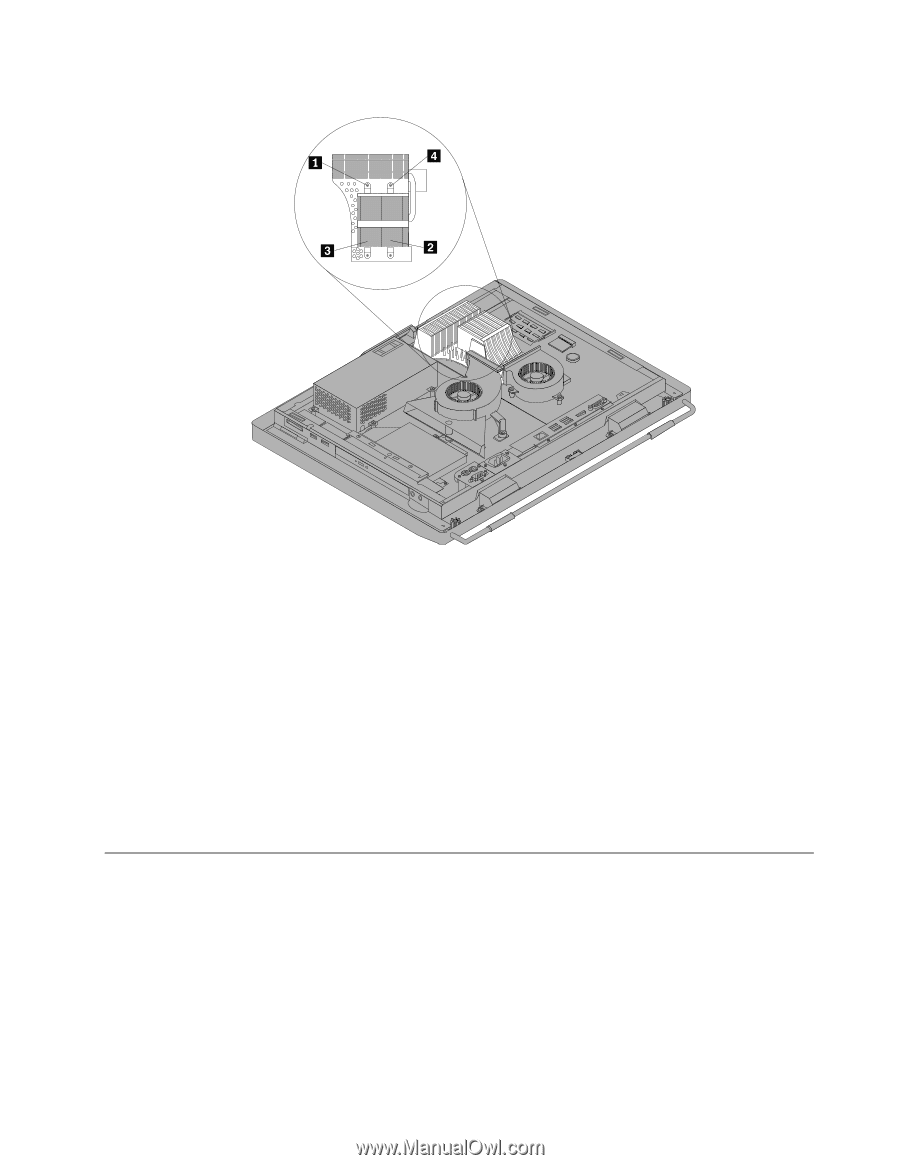
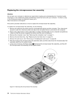
Figure 21. Removing the heat sink 9. Lift the failing heat sink off the system board. Notes: a. You might have to gently twist the heat sink to free it from the microprocessor. b. Do not touch the thermal grease while handling the heat sink. 10. Position the new heat sink on the system board so that the four screws are aligned with the corresponding holes in the system board. 11. Follow the sequence on the heat sink to tighten the four screws to secure the heat sink to the system board, as shown in Figure 21 "Removing the heat sink" on page 87. 12. To reinstall the fan duct, position the fan duct on the heat sink, and then press the fan duct downward until the two tabs on the fan duct are secured into place. 13. Go to "Completing the parts replacement" on page 111. Replacing the microprocessor Attention Do not open your computer or attempt any repair before reading and understanding the "Important safety information" in the ThinkCentre Safety and Warranty Guide that came with your computer. To obtain a copy of the ThinkCentre Safety and Warranty Guide, go to: http://www.lenovo.com/support This section provides instructions on how to replace the microprocessor. Chapter 8. Replacing FRUs 87
-
 1
1 -
2
-
3
-
4
-
5
-
6
-
7
-
8
-
9
-
10
-
11
-
12
-
13
-
14
-
15
-
16
-
17
-
18
-
19
-
20
-
21
-
22
-
23
-
24
-
25
-
26
-
27
-
28
-
29
-
30
-
31
-
32
-
33
-
34
-
35
-
36
-
37
-
38
-
39
-
40
-
41
-
42
-
43
-
44
-
45
-
46
-
47
-
48
-
49
-
50
-
51
-
52
-
53
-
54
-
55
-
56
-
57
-
58
-
59
-
60
-
61
-
62
-
63
-
64
-
65
-
66
-
67
-
68
-
69
-
70
-
71
-
72
-
73
-
74
-
75
-
76
-
77
-
78
-
79
-
80
-
81
-
82
-
83
-
84
-
85
-
86
-
87
-
 88
88 -
 89
89 -
 90
90 -
 91
91 -
 92
92 -
 93
93 -
 94
94 -
 95
95 -
 96
96 -
 97
97 -
 98
98 -
99
-
100
-
101
-
102
-
103
-
104
-
105
-
106
-
107
-
108
-
109
-
110
-
111
-
112
-
113
-
114
-
115
-
116
-
117
-
118
-
119
-
120
-
121
-
122
-
123
-
124
-
125
-
126
-
127
-
128
-
129
-
130
-
131
-
132
-
133
-
134
-
135
-
136
-
137
-
138
-
139
-
140
-
141
-
142
-
143
-
144
-
145
-
146
-
147
-
148
-
149
-
150
-
151
-
152
-
153
-
154
-
155
-
156
-
157
-
158
-
159
-
160
-
161
-
162
-
163
-
164
-
165
-
166
-
167
-
168
-
169
-
170
-
171
-
172
-
173
-
174
-
175
-
176
-
177
-
178
-
179
-
180
-
181
-
182
-
183
-
184
-
185
-
186
-
187
-
188
-
189
-
190
-
191
-
192
-
193
-
194
-
195
-
196
-
197
-
198
-
199
-
200
-
201
-
202
-
203
-
204
-
205
-
206
-
207
-
208
 |
 |