Lenovo ThinkCentre M70z Hardware Maintenance Manual (HMM) - Page 75
System board parts and connectors
 |
View all Lenovo ThinkCentre M70z manuals
Add to My Manuals
Save this manual to your list of manuals |
Page 75 highlights
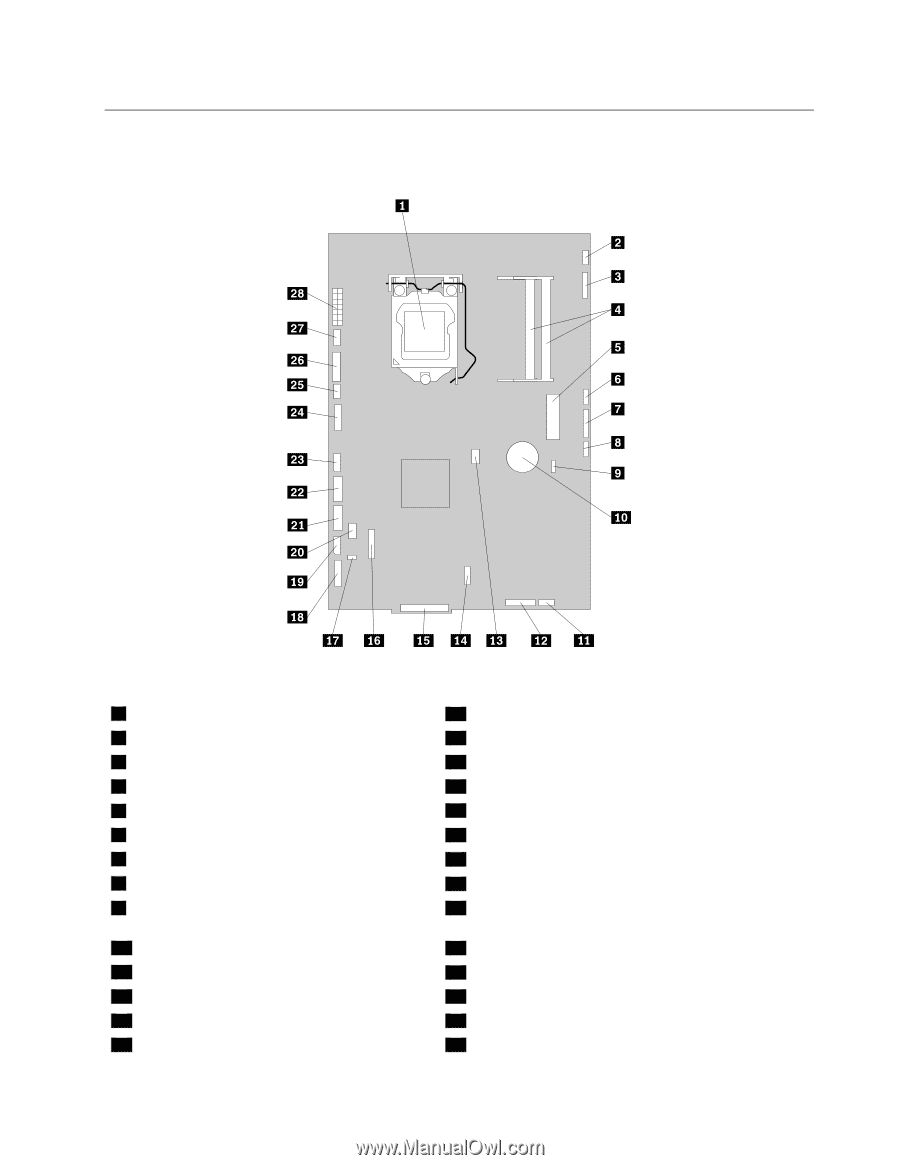
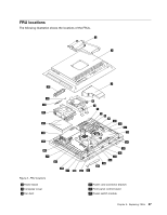
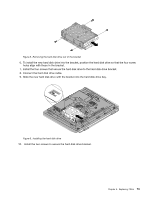
System board parts and connectors The following illustration shows the locations of the system board parts and connectors. Figure 4. System board part and connector locations 1 Microprocessor 2 Multi-touch board cable connector 3 Integrated camera cable connector 4 Memory slots (2) 5 Mini PCI Express slot 6 Ambient light sensor cable connector 7 Bluetooth module cable connector 8 Wireless keyboard and mouse connector 9 Clear CMOS (Complementary Metal Oxide Semiconductor) /Recovery jumper 10 Battery 11 Internal speaker cable connector 12 Power switch cable connector 13 Microprocessor fan connector 14 PIR sensor connector 15 Rear I/O assembly connector 16 COM connector 17 Thermal sensor connector 18 Right I/O assembly cable connector 19 Hard disk drive power connector 20 PS/2 keyboard and mouse connector 21 SATA connector 22 SATA connector 23 Optical drive power connector 24 Low-voltage differential signaling (LVDS) cable connector 25 System fan connector 26 Inverter connector 27 Power supply fan connector 28 Power supply connector Chapter 8. Replacing FRUs 69
-
 1
1 -
2
-
3
-
4
-
5
-
6
-
7
-
8
-
9
-
10
-
11
-
12
-
13
-
14
-
15
-
16
-
17
-
18
-
19
-
20
-
21
-
22
-
23
-
24
-
25
-
26
-
27
-
28
-
29
-
30
-
31
-
32
-
33
-
34
-
35
-
36
-
37
-
38
-
39
-
40
-
41
-
42
-
43
-
44
-
45
-
46
-
47
-
48
-
49
-
50
-
51
-
52
-
53
-
54
-
55
-
56
-
57
-
58
-
59
-
60
-
61
-
62
-
63
-
64
-
65
-
66
-
67
-
68
-
69
-
 70
70 -
 71
71 -
 72
72 -
 73
73 -
 74
74 -
 75
75 -
 76
76 -
 77
77 -
 78
78 -
 79
79 -
 80
80 -
81
-
82
-
83
-
84
-
85
-
86
-
87
-
88
-
89
-
90
-
91
-
92
-
93
-
94
-
95
-
96
-
97
-
98
-
99
-
100
-
101
-
102
-
103
-
104
-
105
-
106
-
107
-
108
-
109
-
110
-
111
-
112
-
113
-
114
-
115
-
116
-
117
-
118
-
119
-
120
-
121
-
122
-
123
-
124
-
125
-
126
-
127
-
128
-
129
-
130
-
131
-
132
-
133
-
134
-
135
-
136
-
137
-
138
-
139
-
140
-
141
-
142
-
143
-
144
-
145
-
146
-
147
-
148
-
149
-
150
-
151
-
152
-
153
-
154
-
155
-
156
-
157
-
158
-
159
-
160
-
161
-
162
-
163
-
164
-
165
-
166
-
167
-
168
-
169
-
170
-
171
-
172
-
173
-
174
-
175
-
176
-
177
-
178
-
179
-
180
-
181
-
182
-
183
-
184
-
185
-
186
-
187
-
188
-
189
-
190
-
191
-
192
-
193
-
194
-
195
-
196
-
197
-
198
-
199
-
200
-
201
-
202
-
203
-
204
-
205
-
206
-
207
-
208
 |
 |