Lenovo ThinkCentre M70z Hardware Maintenance Manual (HMM) - Page 113
Reinstall the battery. See Replacing the battery
 |
View all Lenovo ThinkCentre M70z manuals
Add to My Manuals
Save this manual to your list of manuals |
Page 113 highlights
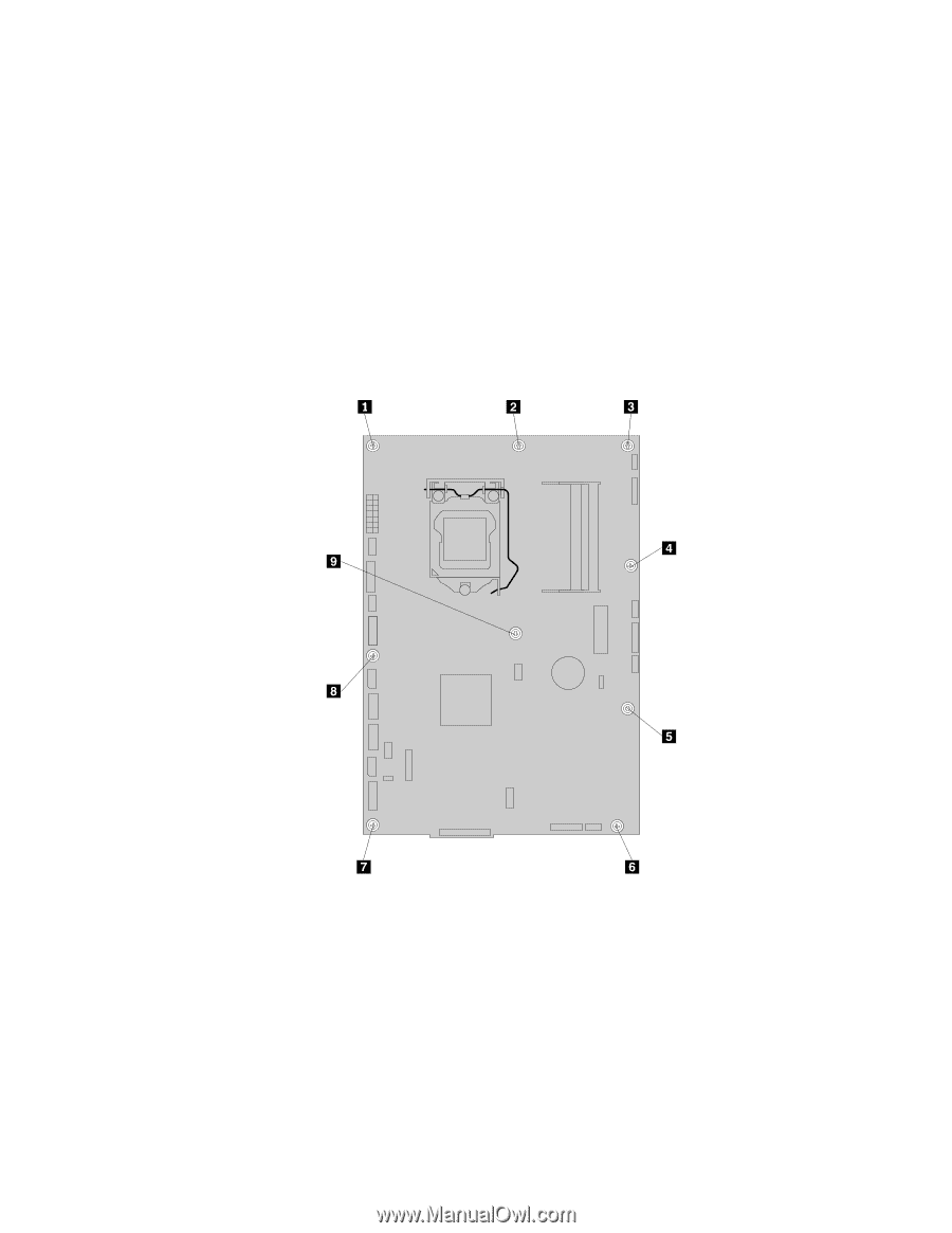
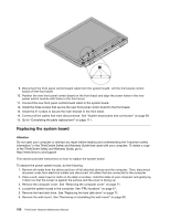
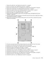
7. Remove the system fan. See "Replacing the system fan" on page 82. 8. Remove the heat sink. See "Replacing the heat sink" on page 85. 9. Remove the microprocessor fan. See "Replacing the microprocessor fan assembly" on page 84. 10. Remove the microprocessor. See "Replacing the microprocessor" on page 87. 11. Remove the memory module. See "Installing or replacing a memory module" on page 91. 12. Remove the WI-FI card. See "Replacing the WI-FI card" on page 94. 13. Remove the battery. See "Replacing the battery" on page 93. 14. Remove the rear I/O assembly to gain access to the system board. See "Replacing the rear I/O assembly" on page 102. 15. Note the locations of all cable connections on the system board and disconnect all cables. See "System board parts and connectors" on page 69. 16. Remove the nine screws that secure the system board to the main bracket. Carefully lift the system board out of the chassis. 17. Place the new system board into the chassis and align the screw holes with those in the chassis. 18. Install the nine screws that secure the system board to the main bracket. 19. Reinstall the rear I/O assembly. See "Replacing the rear I/O assembly" on page 102. 20. Reinstall the battery. See "Replacing the battery" on page 93. 21. Reinstall the WI-FI card. See "Replacing the WI-FI card" on page 94. 22. Reinstall the memory module. See "Installing or replacing a memory module" on page 91. 23. Reinstall the microprocessor. See "Replacing the microprocessor" on page 87. 24. Reinstall the microprocessor fan. See "Replacing the microprocessor fan assembly" on page 84. 25. Reinstall the heat sink. See "Replacing the heat sink" on page 85. 26. Reinstall the system fan. See "Replacing the system fan" on page 82. Chapter 8. Replacing FRUs 107
-
 1
1 -
2
-
3
-
4
-
5
-
6
-
7
-
8
-
9
-
10
-
11
-
12
-
13
-
14
-
15
-
16
-
17
-
18
-
19
-
20
-
21
-
22
-
23
-
24
-
25
-
26
-
27
-
28
-
29
-
30
-
31
-
32
-
33
-
34
-
35
-
36
-
37
-
38
-
39
-
40
-
41
-
42
-
43
-
44
-
45
-
46
-
47
-
48
-
49
-
50
-
51
-
52
-
53
-
54
-
55
-
56
-
57
-
58
-
59
-
60
-
61
-
62
-
63
-
64
-
65
-
66
-
67
-
68
-
69
-
70
-
71
-
72
-
73
-
74
-
75
-
76
-
77
-
78
-
79
-
80
-
81
-
82
-
83
-
84
-
85
-
86
-
87
-
88
-
89
-
90
-
91
-
92
-
93
-
94
-
95
-
96
-
97
-
98
-
99
-
100
-
101
-
102
-
103
-
104
-
105
-
106
-
107
-
 108
108 -
 109
109 -
 110
110 -
 111
111 -
 112
112 -
 113
113 -
 114
114 -
 115
115 -
 116
116 -
 117
117 -
 118
118 -
119
-
120
-
121
-
122
-
123
-
124
-
125
-
126
-
127
-
128
-
129
-
130
-
131
-
132
-
133
-
134
-
135
-
136
-
137
-
138
-
139
-
140
-
141
-
142
-
143
-
144
-
145
-
146
-
147
-
148
-
149
-
150
-
151
-
152
-
153
-
154
-
155
-
156
-
157
-
158
-
159
-
160
-
161
-
162
-
163
-
164
-
165
-
166
-
167
-
168
-
169
-
170
-
171
-
172
-
173
-
174
-
175
-
176
-
177
-
178
-
179
-
180
-
181
-
182
-
183
-
184
-
185
-
186
-
187
-
188
-
189
-
190
-
191
-
192
-
193
-
194
-
195
-
196
-
197
-
198
-
199
-
200
-
201
-
202
-
203
-
204
-
205
-
206
-
207
-
208
 |
 |