Lenovo ThinkCentre M70z Hardware Maintenance Manual (HMM) - Page 114
of the microprocessor socket cover with, Note the orientation of the socket cover. Align the notches
 |
View all Lenovo ThinkCentre M70z manuals
Add to My Manuals
Save this manual to your list of manuals |
Page 114 highlights
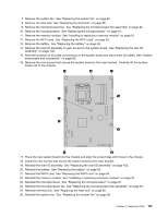
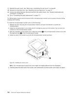
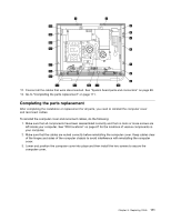
27. Reinstall the wall mount. See "Removing or reinstalling the wall mount" on page 80. 28. Reinstall the hard disk drive. See "Replacing the hard disk drive" on page 72. 29. Connect all cables that were disconnected from the system board. See "System board parts and connectors" on page 69. 30. Go to "Completing the parts replacement" on page 111. The failing system board must be returned with a microprocessor socket cover to protect the pins during shipping and handling. To install the microprocessor socket cover, do the following: 1. Release the lever securing the microprocessor retainer and open the retainer to access the microprocessor. 2. Grasp the microprocessor on the sides and lift it straight up and out of the socket. Do not touch the contacts on the microprocessor socket. 3. Note the orientation of the socket cover. Align the notches 1 of the microprocessor socket cover with the alignment keys 2 of the microprocessor socket. 4. Install one side of the socket cover into the microprocessor socket as shown. Figure 38. Installing the socket cover Note: Your microprocessor socket and cover might look slightly different from the illustration. 5. Carefully press the other side of the socket cover downwards until the socket cover snaps into place. 108 ThinkCentre Hardware Maintenance Manual
-
 1
1 -
2
-
3
-
4
-
5
-
6
-
7
-
8
-
9
-
10
-
11
-
12
-
13
-
14
-
15
-
16
-
17
-
18
-
19
-
20
-
21
-
22
-
23
-
24
-
25
-
26
-
27
-
28
-
29
-
30
-
31
-
32
-
33
-
34
-
35
-
36
-
37
-
38
-
39
-
40
-
41
-
42
-
43
-
44
-
45
-
46
-
47
-
48
-
49
-
50
-
51
-
52
-
53
-
54
-
55
-
56
-
57
-
58
-
59
-
60
-
61
-
62
-
63
-
64
-
65
-
66
-
67
-
68
-
69
-
70
-
71
-
72
-
73
-
74
-
75
-
76
-
77
-
78
-
79
-
80
-
81
-
82
-
83
-
84
-
85
-
86
-
87
-
88
-
89
-
90
-
91
-
92
-
93
-
94
-
95
-
96
-
97
-
98
-
99
-
100
-
101
-
102
-
103
-
104
-
105
-
106
-
107
-
108
-
 109
109 -
 110
110 -
 111
111 -
 112
112 -
 113
113 -
 114
114 -
 115
115 -
 116
116 -
 117
117 -
 118
118 -
 119
119 -
120
-
121
-
122
-
123
-
124
-
125
-
126
-
127
-
128
-
129
-
130
-
131
-
132
-
133
-
134
-
135
-
136
-
137
-
138
-
139
-
140
-
141
-
142
-
143
-
144
-
145
-
146
-
147
-
148
-
149
-
150
-
151
-
152
-
153
-
154
-
155
-
156
-
157
-
158
-
159
-
160
-
161
-
162
-
163
-
164
-
165
-
166
-
167
-
168
-
169
-
170
-
171
-
172
-
173
-
174
-
175
-
176
-
177
-
178
-
179
-
180
-
181
-
182
-
183
-
184
-
185
-
186
-
187
-
188
-
189
-
190
-
191
-
192
-
193
-
194
-
195
-
196
-
197
-
198
-
199
-
200
-
201
-
202
-
203
-
204
-
205
-
206
-
207
-
208
 |
 |
