Panasonic AV-UHS500 4K Switcher Operating Instructions - Page 16
Installation and connections, Be sure to ask your dealer.
 |
View all Panasonic AV-UHS500 manuals
Add to My Manuals
Save this manual to your list of manuals |
Page 16 highlights
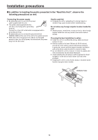
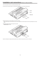
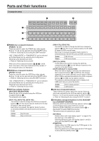
Installation and connections (Be sure to ask your dealer.) 1 Turn off the power of the unit, and disconnect the power cable. 2 Loosen the four screws of SLOT A or SLOT B at the back of the unit, and remove the blank panel. SLOT B SLOT A Blank panel Screw Screw 3 Align the optional unit with the guide rails, and insert it slowly. Insert it until it will go no further. Take care not to exert excessive force while doing this since that may damage the connector inside. 4 Mount the optional unit in place using the four screws. Clamping torque: 0.7 N•m Screw Screw 5 After connecting the necessary cables, plug the power cable into the power outlet, and turn on the power. 16
-
 1
1 -
2
-
3
-
4
-
5
-
6
-
7
-
8
-
9
-
10
-
 11
11 -
 12
12 -
 13
13 -
 14
14 -
 15
15 -
 16
16 -
 17
17 -
 18
18 -
 19
19 -
 20
20 -
 21
21 -
22
-
23
-
24
-
25
-
26
-
27
-
28
-
29
-
30
-
31
-
32
-
33
-
34
-
35
-
36
-
37
-
38
-
39
-
40
-
41
-
42
-
43
-
44
-
45
-
46
-
47
-
48
-
49
-
50
-
51
-
52
-
53
-
54
-
55
-
56
-
57
-
58
-
59
-
60
-
61
-
62
-
63
-
64
-
65
-
66
-
67
-
68
-
69
-
70
-
71
-
72
-
73
-
74
-
75
-
76
-
77
-
78
-
79
-
80
-
81
-
82
-
83
-
84
-
85
-
86
-
87
-
88
-
89
-
90
-
91
-
92
-
93
-
94
-
95
-
96
-
97
-
98
-
99
-
100
-
101
-
102
-
103
-
104
-
105
-
106
-
107
-
108
-
109
-
110
-
111
-
112
-
113
-
114
-
115
-
116
-
117
-
118
-
119
-
120
-
121
-
122
-
123
-
124
-
125
-
126
-
127
-
128
-
129
-
130
-
131
-
132
-
133
-
134
-
135
-
136
-
137
-
138
-
139
-
140
-
141
-
142
-
143
-
144
-
145
-
146
-
147
-
148
-
149
-
150
-
151
-
152
-
153
-
154
-
155
-
156
-
157
-
158
-
159
-
160
-
161
-
162
-
163
-
164
-
165
-
166
-
167
-
168
-
169
-
170
-
171
-
172
-
173
-
174
-
175
-
176
-
177
-
178
-
179
-
180
-
181
-
182
-
183
-
184
-
185
-
186
-
187
-
188
 |
 |

16
Installation and connections
(Be sure to ask your dealer.)
1
Turn off the power of the unit, and disconnect the power cable.
2
Loosen the four screws of SLOT A or SLOT B at the back of the unit, and remove the blank panel.
Screw
Blank panel
Screw
SLOT A
SLOT B
3
Align the optional unit with the guide rails, and insert it slowly.
Insert it until it will go no further. Take care not to exert excessive force while doing this since that may damage the connector
inside.
4
Mount the optional unit in place using the four screws.
Clamping torque:
0.7 N•m
Screw
Screw
5
After connecting the necessary cables, plug the power cable into the power outlet, and turn on the power.