Pioneer 141FD Owner's Manual - Page 7
Control Options: Get to Know Your Flat Panel Display - pro
 |
UPC - 012562905761
View all Pioneer 141FD manuals
Add to My Manuals
Save this manual to your list of manuals |
Page 7 highlights
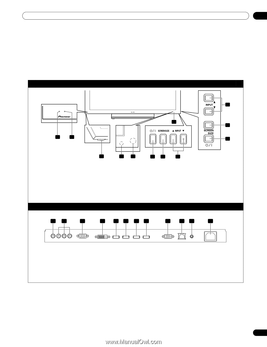
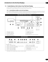
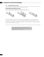
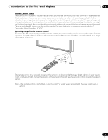
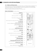
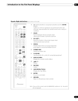
Introduction to the Flat Panel Displays 01 1.2 Control Options: Get to Know Your Flat Panel Display You can operate your flat panel display from the panel buttons or with the remote control. The following sections provide button locations/operations for the panel and the remote control. 1.2.1 Control Buttons and More on the Flat Panel Display Your flat panel display has buttons, indicators, and sensors on the lower front bezel with more buttons on the rear panel. Refer to the drawings below for specific locations and functions. Or, to identify back ports and terminals only, check the terminal position sheet located near the panel's terminal compartment. PRO-141FD/PRO-101FD: Face of Panel 1 2 1 - Power On indicator 2 - STANDBY indicator 3 - Power On () button 4 - Room Light sensor 5 - Remote Control sensor (upper bank) 12 3 8 9 7 6 3 45 67 8 PRO-101FD (Bottom of the rear panel) PRO-141FD (Right side) 6 - STANDBY/ON button 7 - SCREEN SIZE button 8 - INPUT buttons 9 - Bezel (some call it the front frame) Back of the Panel 4 56 78 9 10 11 12 (from left to right) 1 - INPUT 1 terminal (Video) 2 - INPUT 2 terminals (Component, Y, CB/PB, CR/PR) 3 - INPUT 3 terminal (Analog RGB) 4 - INPUT 4 terminal (DVI-D) 5 - INPUT 5 terminal (HDMI) 6 - INPUT 6 terminal (HDMI) 7 - INPUT 7 terminal (HDMI) 8 - INPUT 8 terminal (HDMI) 9 - RS-232C terminal (for factory use) 10 - LAN terminal 11 - IR REPEATER OUT terminal 12 - AC In terminal Terminals on the rear panel are common to both models. 7 En
-
 1
1 -
 2
2 -
 3
3 -
 4
4 -
 5
5 -
 6
6 -
 7
7 -
 8
8 -
 9
9 -
 10
10 -
 11
11 -
 12
12 -
13
-
14
-
15
-
16
-
17
-
18
-
19
-
20
-
21
-
22
-
23
-
24
-
25
-
26
-
27
-
28
-
29
-
30
-
31
-
32
-
33
-
34
-
35
-
36
-
37
-
38
-
39
-
40
-
41
-
42
-
43
-
44
-
45
-
46
-
47
-
48
-
49
-
50
-
51
-
52
-
53
-
54
-
55
-
56
-
57
-
58
-
59
-
60
-
61
-
62
-
63
-
64
-
65
-
66
-
67
-
68
-
69
-
70
-
71
-
72
-
73
-
74
-
75
-
76
-
77
-
78
-
79
-
80
-
81
-
82
-
83
-
84
-
85
-
86
-
87
-
88
-
89
-
90
-
91
-
92
-
93
-
94
-
95
-
96
-
97
-
98
-
99
-
100
-
101
-
102
-
103
-
104
-
105
-
106
 |
 |