Sharp MX 4501N Installation Manual - Page 22
Turn on the power of the main unit, Off-center adjustment
 |
View all Sharp MX 4501N manuals
Add to My Manuals
Save this manual to your list of manuals |
Page 22 highlights
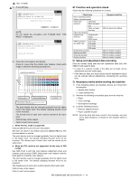
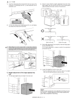
F. Turn on the power of the main unit 1) Connect the earth cord, and insert the power plug of the main unit into the power outlet. 2) Open the front cabinet. Turn ON the power switch in the front cabinet of the main unit. ON 2) This screen allows you to configure the print off-center adjustment value for each paper feed tray. Item E Display Description CS3 Print off-center adjustment value (tray 3) Setting range 1 to 99 Default 50 F CS4 Print off-center adjustment value 1 to 99 50 (tray 4) 3) On the touch panel, press [↓] to select "E: 50 : CS3" or "F: 50 : CS4." 4) Enter the desired adjustment value through the numeric keypad. (This value, which defaults to 50, can be adjusted within the range of 1 to 99). • Reducing the adjustment value by 1 causes the main scan/ print position to shift by 0.1 mm toward the rear. • Increasing the adjustment value by 1 causes the main scan/ print position to shift by 0.1 mm toward the front. 5) After entering the adjustment value, press the [EXECUTE] key on the touch panel to start printing and save the setting. 6) Check that the adjustment pattern image is printed in the correct position. Measure the dimensions of the void areas on the front- and rear-frame sides of the adjustment pattern image, and make sure that the following conditions are met: A 3) Turn ON the power switch on the operation panel. ON ON * For setting the tray size, refer to "Tray size setting" (1-9). G. Off-center adjustment (1) Adjustment with the simulation 1) Run SIM50-10 using the keypad on the main unit. The following screen appears: TEST SIMULATION NO.50-10 PAPER CENTER OFFSET SETUP A : 100 ; BK-MAG A: 100 B : 50 ; MTF [64 - 140] C : 50 D : 50 ; CS1 ; CS2 0 CLOSE EXECUTE OK A-B = 0 -+ 3.0mm B No adjustment is needed if A - B = 0 ±3.0 mm. If the above condition is not met, do the following: 7) Change the adjustment value. (Enter a new adjustment value and press the [OK] key). Changing the adjustment value by 1 shifts the position by approximately 0.1 mm. Repeat steps 4) to 6) until the condition shown in step 6) is satisfied. 8) After you have completed the adjustment, exit from Simulation mode by pressing the [CA] key. MX3500N MX-DEX3/DEX4 2 - 5
-
 1
1 -
2
-
3
-
4
-
5
-
6
-
7
-
8
-
9
-
10
-
11
-
12
-
13
-
14
-
15
-
16
-
 17
17 -
 18
18 -
 19
19 -
 20
20 -
 21
21 -
 22
22 -
 23
23 -
 24
24 -
 25
25 -
 26
26 -
 27
27 -
28
-
29
-
30
-
31
-
32
-
33
-
34
-
35
-
36
-
37
-
38
-
39
-
40
-
41
-
42
-
43
-
44
-
45
-
46
-
47
-
48
-
49
-
50
-
51
-
52
-
53
-
54
-
55
-
56
-
57
-
58
-
59
-
60
-
61
-
62
-
63
-
64
-
65
-
66
-
67
-
68
-
69
-
70
-
71
-
72
 |
 |
