Sharp MX 4501N Installation Manual - Page 51
AR-PN1A/B/C/D
 |
View all Sharp MX 4501N manuals
Add to My Manuals
Save this manual to your list of manuals |
Page 51 highlights
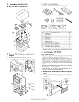
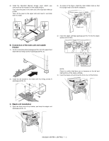
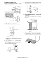
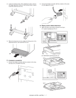
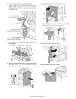
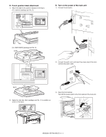
M[8X3]500AN R-PN1A/B/C/D 1. Unpacking A. Removal of the punch unit S2)erOvpiecnetheMfraonntucaablinet. Turn OFF the power switch in the front cabinet of the main unit. OFF 3) Remove the earth cord and disconnect the power plug of the main unit from the power outlet. B. Check the packed items 1) Check that all the items are included in the package. 1 2 3 4 5 6 No. Packed part names 1 Harness A (Purple) 2 Harness B (Orange) 3 Fixing screw (M4 x 6 with tooth lock washer) 4 Dust box label 5 Punch position label (For scanner) * 6 Punch position label (For RSPF) * Quantity 1 1 1 1 1 1 * The punch position labels (No.5 and No.6) and must be those bundled with the MX-FNX2 rather than those bundled with the AR-PN1A/B/C/D. 2. Installation * Before starting installation, check to insure that the data lamp on the operation panel does not light up or blink. A. Turn off the power of the main unit 1) Turn OFF the power switch on the operation panel. 4) Disconnect the connector between the main unit and the saddle finisher. OFF OFF MX3500N AR-PN1A/B/C/D 8 - 1
-
 1
1 -
2
-
3
-
4
-
5
-
6
-
7
-
8
-
9
-
10
-
11
-
12
-
13
-
14
-
15
-
16
-
17
-
18
-
19
-
20
-
21
-
22
-
23
-
24
-
25
-
26
-
27
-
28
-
29
-
30
-
31
-
32
-
33
-
34
-
35
-
36
-
37
-
38
-
39
-
40
-
41
-
42
-
43
-
44
-
45
-
 46
46 -
 47
47 -
 48
48 -
 49
49 -
 50
50 -
 51
51 -
 52
52 -
 53
53 -
 54
54 -
 55
55 -
 56
56 -
57
-
58
-
59
-
60
-
61
-
62
-
63
-
64
-
65
-
66
-
67
-
68
-
69
-
70
-
71
-
72
 |
 |
