Sharp MX 4501N Installation Manual - Page 43
MX-RBX1, MX-FNX2
 |
View all Sharp MX 4501N manuals
Add to My Manuals
Save this manual to your list of manuals |
Page 43 highlights
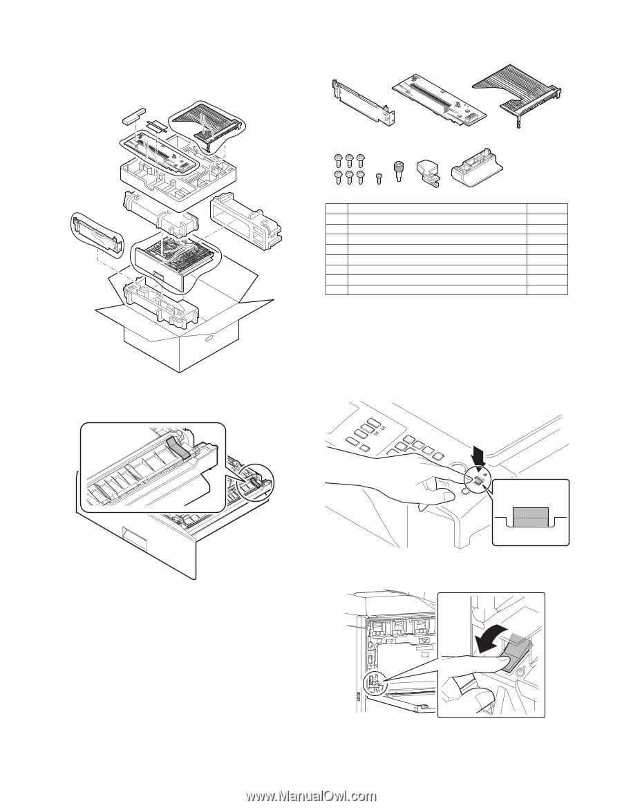
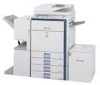
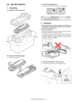
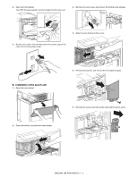
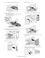
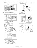
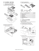
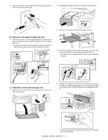
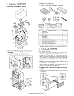
M[7X3]500MN X-RBX1, MX-FNX2 1. Unpacking the MX-RBX1 A. Removal of the interface pass unit B. Removal of the fixing tape 1) Remove the fixing tape. SCe. rCvhieccek tMhaenpuaaclked items 1) Check that all the items are included in the package. 1 2 3 4 56 7 8 No. Packed part names 1 Right cover plate 2 Interface left cabinet 3 Reverse tray 4 Fixing screw A 5 Fixing screw B 6 Ornamental screw 7 Reverse detection actuator 8 Stopper Quantity 1 1 1 6 1 1 1 1 2. Installing the MX-RBX1 * Before starting installation, check to insure that the data lamp on the operation panel does not light up or blink. A. Turn off the power of the main unit 1) Turn OFF the power switch on the operation panel. OFF OFF 2) Open the front cabinet. Turn OFF the power switch in the front cabinet of the main unit. OFF MX3500N MX-RBX1, MX-FNX2 7 - 1
-
 1
1 -
2
-
3
-
4
-
5
-
6
-
7
-
8
-
9
-
10
-
11
-
12
-
13
-
14
-
15
-
16
-
17
-
18
-
19
-
20
-
21
-
22
-
23
-
24
-
25
-
26
-
27
-
28
-
29
-
30
-
31
-
32
-
33
-
34
-
35
-
36
-
37
-
 38
38 -
 39
39 -
 40
40 -
 41
41 -
 42
42 -
 43
43 -
 44
44 -
 45
45 -
 46
46 -
 47
47 -
 48
48 -
49
-
50
-
51
-
52
-
53
-
54
-
55
-
56
-
57
-
58
-
59
-
60
-
61
-
62
-
63
-
64
-
65
-
66
-
67
-
68
-
69
-
70
-
71
-
72
 |
 |