Sharp MX 4501N Installation Manual - Page 46
Unpacking the MX-FNX2, Installing the MX-FNX2
 |
View all Sharp MX 4501N manuals
Add to My Manuals
Save this manual to your list of manuals |
Page 46 highlights
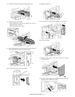
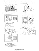
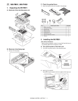
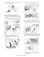
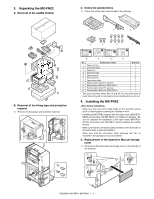
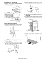
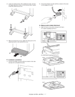
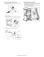
3. Unpacking the MX-FNX2 A. Removal of the saddle finisher C. Check the packed items 1) Check that all the items are included in the package. B. Removal of the fixing tape and protection material 1) Remove the fixing tape and protection material. 1 2 3 4 5 6 7 8 9 10 11 No. Packed part names 1 Paper exit tray 2 Connection plate 3 Staple unit 4 Staple cartridge 5 Fixing screw A 6 Fixing screw B 7 Paper entry guide 8 Staple position label (For scanner) 9 Staple position label (For RSPF/DSPF) 10 Punch position label (For scanner) 11 Punch position label (For RSPF/DSPF) Quantity 1 1 1 1 2 8 1 1 1 1 1 * The punch position labels (No.10 and No.11) should be kept at hand since they will be necessary when installing the punch unit. 4. Installing the MX-FNX2 * Make sure that none of the data lamps on the operation panels are lit or flashing before starting the installation work. * Installing the MX-FNX2 requires that the option desk (MX-DEX1/ DEX2) and junction unit (MX-RBX1) be installed in advance. Be sure to complete the installation of the option desk (MX-DEX1/ DEX2) and junction unit (MX-RBX1) before installing the saddle finisher. * Make sure that the connection plate provided on the front side of the option desk is securely installed. Make sure that the connection plate (package part No. 2) included in the package is securely installed. A. Replacement of the Operation Manual storage cover 1) Remove the Operation Manual storage cover on the left side of the machine. 1 2 2 MX3500N MX-RBX1, MX-FNX2 7 - 4
-
 1
1 -
2
-
3
-
4
-
5
-
6
-
7
-
8
-
9
-
10
-
11
-
12
-
13
-
14
-
15
-
16
-
17
-
18
-
19
-
20
-
21
-
22
-
23
-
24
-
25
-
26
-
27
-
28
-
29
-
30
-
31
-
32
-
33
-
34
-
35
-
36
-
37
-
38
-
39
-
40
-
 41
41 -
 42
42 -
 43
43 -
 44
44 -
 45
45 -
 46
46 -
 47
47 -
 48
48 -
 49
49 -
 50
50 -
 51
51 -
52
-
53
-
54
-
55
-
56
-
57
-
58
-
59
-
60
-
61
-
62
-
63
-
64
-
65
-
66
-
67
-
68
-
69
-
70
-
71
-
72
 |
 |
