Sharp MX 4501N Installation Manual - Page 39
MX-PNX1A/B/C/D
 |
View all Sharp MX 4501N manuals
Add to My Manuals
Save this manual to your list of manuals |
Page 39 highlights
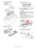
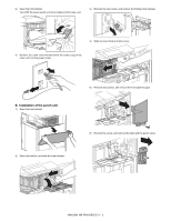
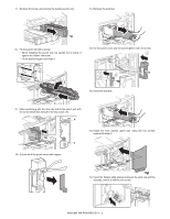
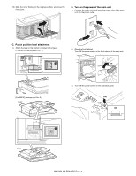
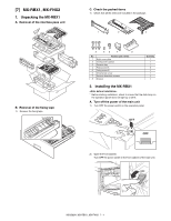
[M6X3]500MN X-PNX1A/B/C/D 1. Unpacking A. Removal of the punch unit SCe. rCvhieccek tMhaenpuaaclked items 1) Check that all the items are included in the package. 1 2 No. Packed part names 1 Punch position label (For scanner) 2 Punch position label (For RSPF/DSPF) Quantity 1 1 2. Installation * When the punch unit is installed together with installation of the MX-FNX1 (inner finisher), first install the inner finisher, and then install the punch unit. * Before starting installation, check to insure that the data lamp on the operation panel does not light up or blink. * Do not install the punch unit first because doing so would cause interference between the inner finisher slide rail and the punch unit drawer connector (possibly resulting in failure) when you attempt to install the inner finisher. B. Removal of the fixing tape 1) Remove the fixing tape. A. Turn off the power of the main unit 1) Turn OFF the power switch on the operation panel. OFF OFF MX3500N MX-PNX1A/B/C/D 6 - 1
-
 1
1 -
2
-
3
-
4
-
5
-
6
-
7
-
8
-
9
-
10
-
11
-
12
-
13
-
14
-
15
-
16
-
17
-
18
-
19
-
20
-
21
-
22
-
23
-
24
-
25
-
26
-
27
-
28
-
29
-
30
-
31
-
32
-
33
-
 34
34 -
 35
35 -
 36
36 -
 37
37 -
 38
38 -
 39
39 -
 40
40 -
 41
41 -
 42
42 -
 43
43 -
 44
44 -
45
-
46
-
47
-
48
-
49
-
50
-
51
-
52
-
53
-
54
-
55
-
56
-
57
-
58
-
59
-
60
-
61
-
62
-
63
-
64
-
65
-
66
-
67
-
68
-
69
-
70
-
71
-
72
 |
 |
