Sharp MX 4501N Installation Manual - Page 58
Remove the rear cabinet., Remove the SCN IN PWB., Attach the DOCC PWB., Attach the rear cabinet.
 |
View all Sharp MX 4501N manuals
Add to My Manuals
Save this manual to your list of manuals |
Page 58 highlights
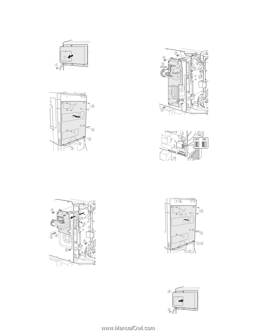
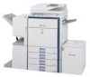
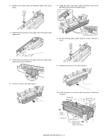
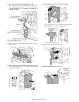
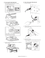
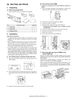
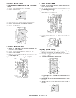
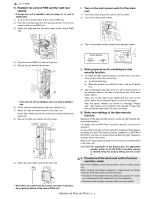
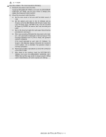
D. Remove the rear cabinet. • If the fax box unit is installed, carry out steps 1) and 2) additionally. 1) Remove the screw that secures the fax box unit. 2) Remove the fax box unit. F. Attach the DOCC PWB. 1) Connect the connector of the DOCC PWB to the 30-pin connector of the Mother PWB. 2) Use the four screws that have been removed in step E-2) and 5) to secure the DOCC PWB. 3) Connect the 12-pin and 15-pin connectors of the main unit to the connectors on the DOCC PWB. 3) Loosen the four lower screws that secure the rear cabinet. 4) Remove the seven screws indicated in the illustration. 5) Remove the rear cabinet. 4) Ensure that pins 1 and 2 of the DIP switch on the DOCC PWB are OFF. E. Remove the SCN IN PWB. 1) Remove the 12-pin and 15-pin connectors of the main unit connected to the SCN IN PWB. 2) Remove the three screws that secure the SCN IN PWB. 3) Remove the SCN IN PWB. 4) Attach one of the three screws that have been removed in step 2) to the Mother PWB. 5) Remove the two screws for securing the DOCC PWB. G. Attach the rear cabinet. 1) Hang the four mounting portions at the lower part of the rear cabinet on the four screws that have been loosened. 2) Secure the rear cabinet with the seven screws that have been removed in step D-4). 3) Tighten the screws that have been loosened. • If the fax box unit is installed, carry out steps 4) and 5) additionally. 4) Hang the fax box unit that has been removed in step D on the step screw. 5) Secure the fax box unit with the screw which was removed in step D-1). MX3500N MX-FRX2, MX-FRX2U 9 - 2
-
 1
1 -
2
-
3
-
4
-
5
-
6
-
7
-
8
-
9
-
10
-
11
-
12
-
13
-
14
-
15
-
16
-
17
-
18
-
19
-
20
-
21
-
22
-
23
-
24
-
25
-
26
-
27
-
28
-
29
-
30
-
31
-
32
-
33
-
34
-
35
-
36
-
37
-
38
-
39
-
40
-
41
-
42
-
43
-
44
-
45
-
46
-
47
-
48
-
49
-
50
-
51
-
52
-
 53
53 -
 54
54 -
 55
55 -
 56
56 -
 57
57 -
 58
58 -
 59
59 -
 60
60 -
 61
61 -
 62
62 -
 63
63 -
64
-
65
-
66
-
67
-
68
-
69
-
70
-
71
-
72
 |
 |