Sharp MX 4501N Installation Manual - Page 45
Fix the stopper package part No. 8 with the fixing screw B
 |
View all Sharp MX 4501N manuals
Add to My Manuals
Save this manual to your list of manuals |
Page 45 highlights
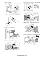
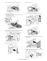
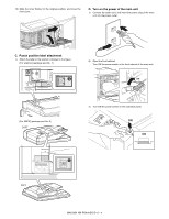
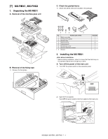
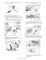
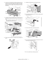
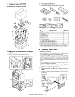
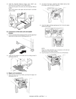
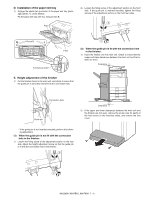
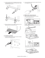
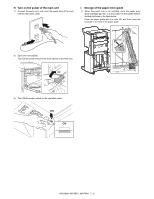
6) Insert the rib of the interface left cabinet (package part No. 2) into the slit on the lower surface of the scanner left cabinet. Install the interface left cabinet with the fixing screw A (package part No. 4) of the paper exit tray which was removed in procedure 4). 9) Install the front cabinet upper, and fix with the screws. 7) Insert the reverse tray (package part No. 3) along the groove in the interface left cabinet and the top surface of the right cover plate. * When inserting the reverse tray, check to insure that the switch guide of the reverse tray is up. 10) Fix the stopper (package part No. 8) with the fixing screw B (package part No. 5). 11) Insert the interface pass unit along the guide rail. 8) Fix the reverse tray with the ornamental screw (package part No. 6). 12) Fix the interface pass disconnection preventing lever with the fixing screw A (package part No. 4). 13) Go to the saddle finisher installing procedure. MX3500N MX-RBX1, MX-FNX2 7 - 3
-
 1
1 -
2
-
3
-
4
-
5
-
6
-
7
-
8
-
9
-
10
-
11
-
12
-
13
-
14
-
15
-
16
-
17
-
18
-
19
-
20
-
21
-
22
-
23
-
24
-
25
-
26
-
27
-
28
-
29
-
30
-
31
-
32
-
33
-
34
-
35
-
36
-
37
-
38
-
39
-
 40
40 -
 41
41 -
 42
42 -
 43
43 -
 44
44 -
 45
45 -
 46
46 -
 47
47 -
 48
48 -
 49
49 -
 50
50 -
51
-
52
-
53
-
54
-
55
-
56
-
57
-
58
-
59
-
60
-
61
-
62
-
63
-
64
-
65
-
66
-
67
-
68
-
69
-
70
-
71
-
72
 |
 |
