Sharp MX 4501N Installation Manual - Page 26
Connection of the main unit and the large, capacity tray unit
 |
View all Sharp MX 4501N manuals
Add to My Manuals
Save this manual to your list of manuals |
Page 26 highlights
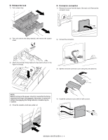
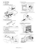
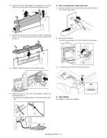
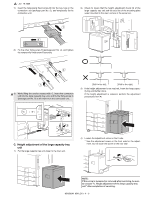
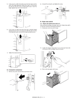
2) Open the front cabinet. Turn OFF the power switch in the front cabinet of the main unit. OFF 3) Disengage the pawl, and remove the right adjuster. 1 1 3) Remove the earth cord and disconnect the power plug of the main unit from the power outlet. 2 4) Remove the screw cap, and remove the screw. 1 2 B. Connection of the main unit and the large capacity tray unit 1) Install the mounting plate upper (package part No. 1) to the right side of the main unit with the fixing screw A (package part No. 3). * When installing, put the rubber section of the mounting plate upper on the lower side. 5) Remove the cover. 6) Temporarily fix the fixing screw B (package part No. 4) midway. 2) Remove the right door cover from the machine. 1 3 2 3 MX3500N MX-LCX1 4 - 2
-
 1
1 -
2
-
3
-
4
-
5
-
6
-
7
-
8
-
9
-
10
-
11
-
12
-
13
-
14
-
15
-
16
-
17
-
18
-
19
-
20
-
 21
21 -
 22
22 -
 23
23 -
 24
24 -
 25
25 -
 26
26 -
 27
27 -
 28
28 -
 29
29 -
 30
30 -
 31
31 -
32
-
33
-
34
-
35
-
36
-
37
-
38
-
39
-
40
-
41
-
42
-
43
-
44
-
45
-
46
-
47
-
48
-
49
-
50
-
51
-
52
-
53
-
54
-
55
-
56
-
57
-
58
-
59
-
60
-
61
-
62
-
63
-
64
-
65
-
66
-
67
-
68
-
69
-
70
-
71
-
72
 |
 |
