Sharp MX 4501N Installation Manual - Page 24
Turn on the power of the main unit., Tray setting
 |
View all Sharp MX 4501N manuals
Add to My Manuals
Save this manual to your list of manuals |
Page 24 highlights
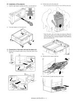
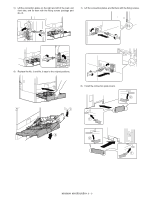
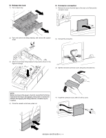
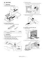
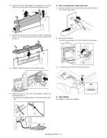
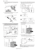
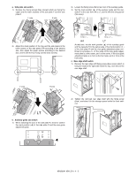
3) Remove the screw. Disengage the engagement in the front side then in the rear side, and remove the paper exit cover. 4 1 2 C. Turn on the power of the main unit. 1) Connect the earth cord, and insert the power plug of the main unit into the power outlet. 3 4) Connect the connector, and install the exit roller unit (package part No. 1). Use the screw which was removed in step 3) and fix the unit. 2) Open the front cabinet. Turn ON the power switch in the front cabinet of the main unit. ON 5) Install the connector cover, and fix it with the screw. 3) Turn ON the power switch on the operation panel. ON ON 6) Install the exit tray unit (A) and the full detection actuator (B) (package part No. 2). * Be careful of the installing direction of the full detection actuator. D. Tray setting Use SIM26-1 to set the tray YES/NO. B B A MX3500N MX-TRX2 3 - 2
-
 1
1 -
2
-
3
-
4
-
5
-
6
-
7
-
8
-
9
-
10
-
11
-
12
-
13
-
14
-
15
-
16
-
17
-
18
-
 19
19 -
 20
20 -
 21
21 -
 22
22 -
 23
23 -
 24
24 -
 25
25 -
 26
26 -
 27
27 -
 28
28 -
 29
29 -
30
-
31
-
32
-
33
-
34
-
35
-
36
-
37
-
38
-
39
-
40
-
41
-
42
-
43
-
44
-
45
-
46
-
47
-
48
-
49
-
50
-
51
-
52
-
53
-
54
-
55
-
56
-
57
-
58
-
59
-
60
-
61
-
62
-
63
-
64
-
65
-
66
-
67
-
68
-
69
-
70
-
71
-
72
 |
 |
