Sharp MX 4501N Installation Manual - Page 48
Installation of the paper exit tray, Height adjustment of the finisher
 |
View all Sharp MX 4501N manuals
Add to My Manuals
Save this manual to your list of manuals |
Page 48 highlights
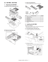
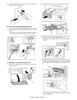
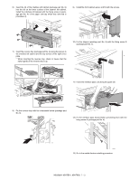
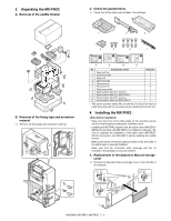
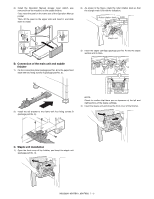
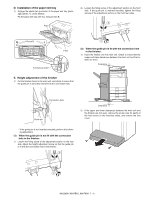
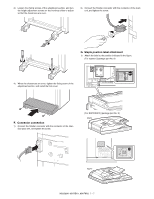
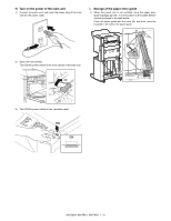
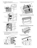
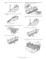
D. Installation of the paper exit tray 1) Engage the pawls (two positions) of the paper exit tray (package part No. 1) on the finisher. Fix the paper exit tray with four fixing screws B. Pawl 2) Loosen the fixing screw of the adjustment section on the front side. If the guide pin is inserted smoothly, tighten the fixing screws of the adjustment section on the front/rear sides. 2 Screw B Positioning dowel Pawl 1 (2) When the guide pin is fit with the connection hole in the finisher: 1) Insert the finisher into the main unit. Check to insure that the upper and lower clearances between the main unit and the finisher are even. Clearance E. Height adjustment of the finisher 1) Put the finisher closer to the main unit, and check to insure that the guide pin is smoothly inserted into the connection hole. Connection hole Guide pin Clearance 2) If the upper and lower clearances between the main unit and the finisher are not even, remove the screw (one for each) of the foot covers on the front/rear sides, and remove the foot cover. * If the guide pin is not inserted smoothly, perform the following adjustment. (1) When the guide pin is not fit with the connection hole in the finisher: 1) Loosen the fixing screw of the adjustment section on the rear side. Adjust the height adjustment screw so that the guide pin is fit with the connection hole in the finisher. 2 1 MX3500N MX-RBX1, MX-FNX2 7 - 6
-
 1
1 -
2
-
3
-
4
-
5
-
6
-
7
-
8
-
9
-
10
-
11
-
12
-
13
-
14
-
15
-
16
-
17
-
18
-
19
-
20
-
21
-
22
-
23
-
24
-
25
-
26
-
27
-
28
-
29
-
30
-
31
-
32
-
33
-
34
-
35
-
36
-
37
-
38
-
39
-
40
-
41
-
42
-
 43
43 -
 44
44 -
 45
45 -
 46
46 -
 47
47 -
 48
48 -
 49
49 -
 50
50 -
 51
51 -
 52
52 -
 53
53 -
54
-
55
-
56
-
57
-
58
-
59
-
60
-
61
-
62
-
63
-
64
-
65
-
66
-
67
-
68
-
69
-
70
-
71
-
72
 |
 |
