Sony VGX-XL1 User Guide - Page 22
Optical S/PDIF OUT & Coaxial S/PDIF OUT, Component Video OUT 480i, 480p, 720P - setup
 |
View all Sony VGX-XL1 manuals
Add to My Manuals
Save this manual to your list of manuals |
Page 22 highlights
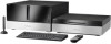
USB 2.0 (x2) Universal Serial Bus Connects to a device which supports the USB standard. The connector supports the USB 2.0 standard and can also be connected to a device which supports the USB 1.1 standard. Optical S/PDIF IN Connection for Audio In. i.LINK®a (x2) Your VAIO® computer is equipped with one 4-pin (front panel) and two 6-pin (back panel) i.LINK® port. A 4-pin i.LINK port cannot supply power to a connected i.LINK® device. A 6-pin i.LINK port can supply power (10V to 12V) to a connected i.LINK® device, if the device is equipped with a 6-pin connector. Optical S/PDIF OUT & Coaxial S/PDIF OUT Connections for Audio Out. Wireless LAN Antenna Connection for Wireless LAN Antenna. Infrared Transmitter OUT (x2) Controls VCR, Setup box, and other devices in MCE. Component Video OUT (480i, 480p,720P) Connections for Video Out. Power Cord Connection for supplied power cord. a. i.LINK is a trademark of Sony used only to designate that a product contains an IEEE1394 connection. The i.LINK connection may vary depending on the software applications, operating system and compatible i.LINK devices. All products with an i.LINK connection may not communicate with each other. Please refer to the documentation that comes with any device having an i.LINK connection for information on compatibility, operating conditions and proper connection. For information on any Sony device having an i.LINK connection, contact Sony at 1-800-686-7669. VGX-XL1 Digital Living System 19
-
 1
1 -
2
-
3
-
4
-
5
-
6
-
7
-
8
-
9
-
10
-
11
-
12
-
13
-
14
-
15
-
16
-
 17
17 -
 18
18 -
 19
19 -
 20
20 -
 21
21 -
 22
22 -
 23
23 -
 24
24 -
 25
25 -
 26
26 -
 27
27 -
28
-
29
-
30
-
31
-
32
-
33
-
34
-
35
-
36
-
37
-
38
-
39
-
40
-
41
-
42
-
43
-
44
-
45
-
46
-
47
-
48
-
49
-
50
-
51
-
52
-
53
-
54
-
55
-
56
-
57
-
58
-
59
-
60
-
61
-
62
-
63
-
64
-
65
-
66
-
67
-
68
-
69
-
70
-
71
-
72
-
73
-
74
-
75
-
76
-
77
-
78
-
79
-
80
-
81
-
82
-
83
-
84
-
85
-
86
-
87
-
88
-
89
-
90
-
91
-
92
-
93
-
94
-
95
-
96
-
97
-
98
-
99
-
100
-
101
-
102
-
103
-
104
-
105
-
106
-
107
-
108
-
109
-
110
-
111
-
112
-
113
-
114
-
115
-
116
-
117
-
118
-
119
-
120
-
121
-
122
-
123
-
124
-
125
-
126
-
127
-
128
-
129
-
130
-
131
-
132
-
133
-
134
-
135
-
136
-
137
-
138
-
139
-
140
-
141
-
142
-
143
-
144
-
145
-
146
-
147
-
148
-
149
-
150
-
151
-
152
-
153
-
154
-
155
-
156
-
157
-
158
-
159
-
160
-
161
-
162
-
163
-
164
-
165
-
166
-
167
-
168
-
169
-
170
-
171
-
172
-
173
-
174
-
175
 |
 |