Sony VGX-XL1 User Guide - Page 62
Install and remove memory modules, the opposite direction which can cause damage to the memory module
 |
View all Sony VGX-XL1 manuals
Add to My Manuals
Save this manual to your list of manuals |
Page 62 highlights
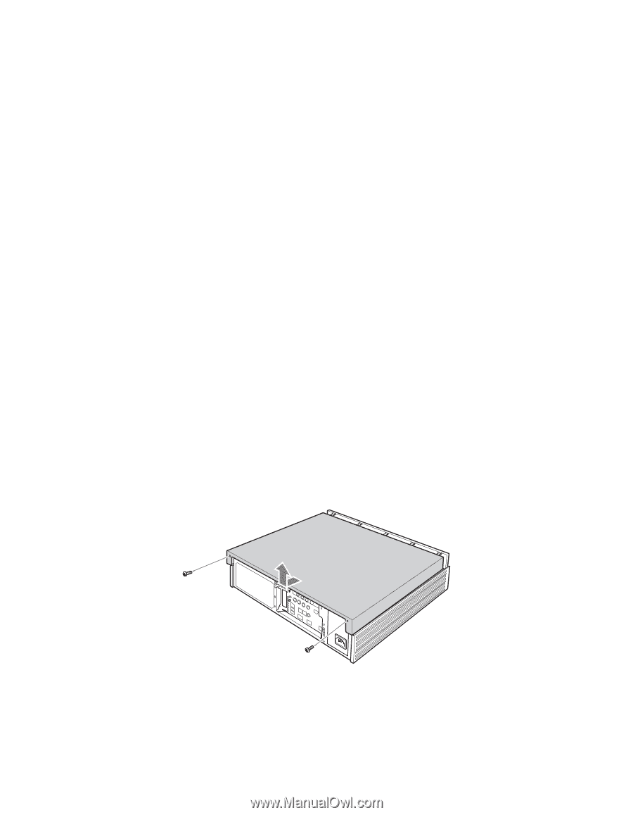
Please be careful of the following when upgrading the memory as the memory slots for this device are separated into two banks. • There are two banks and four slots (two in each bank) available to install memory modules in this device. Each slot can hold a 512 MB memory module. • Install memory modules of the same type, name, speed, and capacity in both slots in the same bank. • Always install from bank 0 when installing memory modules. • Also, refer to the memory module user's manual when installing. • The memory modules have a proper direction. • Properly match the notch area on the edge of the memory module connector and the projections (inside the connector) in the slot. • Please be careful not to forcefully insert the memory module in the slot in the opposite direction which can cause damage to the memory module and the slot or loosen it from the circuit board. Install and remove memory modules 1 Turn off the power to this device and all peripheral devices, and remove the power cord and all cables connecting peripheral devices. Some inside components may be hot. Wait approximately one hour before proceeding to work. 2 Remove the upper cover. Remove the screws at the rear and slide the cover off. VGX-XL1 Digital Living System 59
-
 1
1 -
2
-
3
-
4
-
5
-
6
-
7
-
8
-
9
-
10
-
11
-
12
-
13
-
14
-
15
-
16
-
17
-
18
-
19
-
20
-
21
-
22
-
23
-
24
-
25
-
26
-
27
-
28
-
29
-
30
-
31
-
32
-
33
-
34
-
35
-
36
-
37
-
38
-
39
-
40
-
41
-
42
-
43
-
44
-
45
-
46
-
47
-
48
-
49
-
50
-
51
-
52
-
53
-
54
-
55
-
56
-
 57
57 -
 58
58 -
 59
59 -
 60
60 -
 61
61 -
 62
62 -
 63
63 -
 64
64 -
 65
65 -
 66
66 -
 67
67 -
68
-
69
-
70
-
71
-
72
-
73
-
74
-
75
-
76
-
77
-
78
-
79
-
80
-
81
-
82
-
83
-
84
-
85
-
86
-
87
-
88
-
89
-
90
-
91
-
92
-
93
-
94
-
95
-
96
-
97
-
98
-
99
-
100
-
101
-
102
-
103
-
104
-
105
-
106
-
107
-
108
-
109
-
110
-
111
-
112
-
113
-
114
-
115
-
116
-
117
-
118
-
119
-
120
-
121
-
122
-
123
-
124
-
125
-
126
-
127
-
128
-
129
-
130
-
131
-
132
-
133
-
134
-
135
-
136
-
137
-
138
-
139
-
140
-
141
-
142
-
143
-
144
-
145
-
146
-
147
-
148
-
149
-
150
-
151
-
152
-
153
-
154
-
155
-
156
-
157
-
158
-
159
-
160
-
161
-
162
-
163
-
164
-
165
-
166
-
167
-
168
-
169
-
170
-
171
-
172
-
173
-
174
-
175
 |
 |