Stihl MS 162 Instruction Manual - Page 26
Mounting the Guide Bar and Chain, Quick Chain Adjuster
 |
View all Stihl MS 162 manuals
Add to My Manuals
Save this manual to your list of manuals |
Page 26 highlights
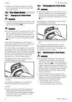
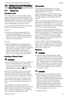
English ► Position the chain in the groove of the guide bar, starting at the tip. ► Make sure that the cutters in the groove on the top side of the guide bar face the tip of the bar. STIHL chains are manufactured with arrows on the tie straps to help the operator deter‐ mine the proper direction of the chain. Arrows on the tie straps on the top of the bar must point toward the bar tip. 6 7 55 10.2.2 10 Assembling the Chain Saw Mounting the Guide Bar and Chain (Quick Chain Adjuster) WARNING ■ The chain has many sharp cutters. If they con‐ tact your flesh, they will cut you, even if the chain is not moving, 5.4. Always wear heavy-duty work gloves when mounting or oth‐ erwise handling the chain, 5.3. 1 3 2 0000097418_001 0000097416_001 8 ► Point the guide bar tip away from the chain sprocket (7). ► Place the chain around the chain sprocket. ► Slide the guide bar (6) over the collar screws (5). The head of the collar screw must protrude into the oblong hole. ► Fit the pin of the tensioning gear in the hole (8) of the guide bar. ► Disengage the chain brake, 12.2. ► Raise the handle (1) of the wingnut (2). ► Turn the wingnut counterclockwise until the chain sprocket cover (3) can be removed. ► Remove the chain sprocket cover. 4 0000099376_001 5 3 6 ► Remove the tensioning gear (4). ► Remove the screw (5). 0000097417_001 ► Direct the drive links into the groove of the guide bar (arrow) while turning the side chain tensioner (3) clockwise until it stops. The guide bar and chain must be firmly and securely mounted on the saw. ► Fit the sprocket cover on the saw so that it is flush with the housing. ► Turn the nut clockwise until the chain sprocket cover is firmly attached to the saw. 6 5 4 ► Position the guide bar (6) on the tensioning gear so that the pins of the tensioning gear fit in the holes of the guide bar. The top and bottom of the guide bar are symmet‐ rical, and the bar may be mounted with the print‐ ing facing up or down. ► Insert the screw (5) and tighten it. 0000098250_001 26 0458-200-8621-A
-
 1
1 -
2
-
3
-
4
-
5
-
6
-
7
-
8
-
9
-
10
-
11
-
12
-
13
-
14
-
15
-
16
-
17
-
18
-
19
-
20
-
 21
21 -
 22
22 -
 23
23 -
 24
24 -
 25
25 -
 26
26 -
 27
27 -
 28
28 -
 29
29 -
 30
30 -
 31
31 -
32
-
33
-
34
-
35
-
36
-
37
-
38
-
39
-
40
-
41
-
42
-
43
-
44
-
45
-
46
-
47
-
48
-
49
-
50
-
51
-
52
-
53
-
54
-
55
-
56
-
57
-
58
-
59
-
60
-
61
-
62
-
63
-
64
-
65
-
66
-
67
-
68
-
69
-
70
-
71
-
72
-
73
-
74
-
75
-
76
-
77
-
78
-
79
-
80
-
81
-
82
-
83
-
84
-
85
-
86
-
87
-
88
-
89
-
90
-
91
-
92
-
93
-
94
-
95
-
96
-
97
-
98
-
99
-
100
-
101
-
102
-
103
-
104
-
105
-
106
-
107
-
108
 |
 |
