Stihl MS 162 Instruction Manual - Page 27
Removing the Guide Bar and Chain, Quick Chain Adjuster
 |
View all Stihl MS 162 manuals
Add to My Manuals
Save this manual to your list of manuals |
Page 27 highlights
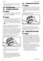
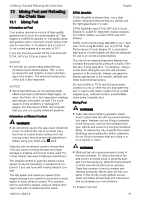
10 Assembling the Chain Saw 4 ► Position the chain in the groove of the guide bar, starting at the tip. ► Make sure that the cutters in the groove on the top side of the guide bar face the tip of the bar. STIHL chains are manufactured with arrows on the tie straps to help the operator deter‐ mine the proper direction of the chain. Arrows on the tie straps on the top of the bar must point toward the bar tip. ► Turn the tensioning gear (4) clockwise until it stops. 4 23 6 ► Point the guide bar tip away from the chain sprocket (2). ► Place the chain around the chain sprocket. ► Slide the guide bar over the collar screw (3). The head of the collar screw must protrude into the oblong hole. ► Disengage the chain brake, 12.2. 4 0000097420_001 0000-GXX-1201-A0 English ► When fitting the chain sprocket cover, the teeth of the adjusting wheel and the tensioning gear must mesh. ► If necessary, turn the adjusting wheel slightly until the chain sprocket cover sits flush against the housing. ► Turn the wingnut clockwise until the chain sprocket cover is firmly attached to the saw. ► Close the handle of the wingnut. 10.2.3 Removing the Guide Bar and Chain ► Unscrew the nut securing the chain sprocket cover. ► Remove the chain sprocket cover. ► Turn the side chain tensioner counter-clock‐ wise until it stops and the chain is loose. ► Remove the guide bar and chain. NOTICE ■ The top and bottom of the guide bar are sym‐ metrical, and the bar may be mounted with the printing facing up or down. Flipping the guide bar each time the chain is sharpened or changed will help reduce uneven wear and extend its service life. 10.2.4 Removing the Guide Bar and Chain (Quick Chain Adjuster) ► Raise the handle of the wingnut. ► Turn the wingnut counterclockwise until the chain sprocket cover can be removed. ► Remove the chain sprocket cover. ► Turn the tensioning gear clockwise until it stops and the chain is loose. ► Remove the guide bar and chain. ► Remove the tensioning gear. ► Remove the screw. NOTICE ■ The top and bottom of the guide bar are sym‐ metrical, and the bar may be mounted with the printing facing up or down. Flipping the guide bar each time the chain is sharpened or changed will help reduce uneven wear and extend its service life. 0000097421_001 ► Direct the drive links into the groove of the guide bar (arrow) while turning the tensioning gear (4) counterclockwise until it stops. The guide bar and chain must be firmly and securely mounted on the saw. ► Fit the sprocket cover on the saw so that it is flush with the housing. 0458-200-8621-A 27
-
 1
1 -
2
-
3
-
4
-
5
-
6
-
7
-
8
-
9
-
10
-
11
-
12
-
13
-
14
-
15
-
16
-
17
-
18
-
19
-
20
-
21
-
 22
22 -
 23
23 -
 24
24 -
 25
25 -
 26
26 -
 27
27 -
 28
28 -
 29
29 -
 30
30 -
 31
31 -
 32
32 -
33
-
34
-
35
-
36
-
37
-
38
-
39
-
40
-
41
-
42
-
43
-
44
-
45
-
46
-
47
-
48
-
49
-
50
-
51
-
52
-
53
-
54
-
55
-
56
-
57
-
58
-
59
-
60
-
61
-
62
-
63
-
64
-
65
-
66
-
67
-
68
-
69
-
70
-
71
-
72
-
73
-
74
-
75
-
76
-
77
-
78
-
79
-
80
-
81
-
82
-
83
-
84
-
85
-
86
-
87
-
88
-
89
-
90
-
91
-
92
-
93
-
94
-
95
-
96
-
97
-
98
-
99
-
100
-
101
-
102
-
103
-
104
-
105
-
106
-
107
-
108
 |
 |
