TP-Link 10GE T1700G-28TQUN V1 User Guide - Page 105
MSTP Instance
 |
View all TP-Link 10GE manuals
Add to My Manuals
Save this manual to your list of manuals |
Page 105 highlights
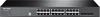
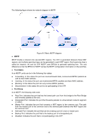
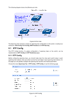
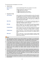
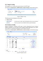
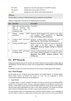
Port Mode: Port Role: Port Status: LAG: Display the spanning tree mode of the port. Displays the role of the port played in the STP Instance. Root Port: Indicates the port that has the lowest path cost from this bridge to the Root Bridge and forwards packets to the root. Designated Port: Indicates the port that forwards packets to a downstream network segment or switch. Master Port: Indicates the port that connects a MST region to the common root. The path from the master port to the common root is the shortest path between this MST region and the common root. Alternate Port: Indicates the port that can be a backup port of a root or master port. Backup Port: Indicates the port that is the backup port of a designated port. Disabled: Indicates the port that is not participating in the STP. Displays the working status of the port. Forwarding: In this status the port can receive/forward data, receive/send BPDU packets as well as learn MAC address. Learning: In this status the port can receive/send BPDU packets and learn MAC address. Blocking: In this status the port can only receive BPDU packets. Disconnected: In this status the port is not participating in the STP. Displays the LAG number which the port belongs to. Note: 1. Configure the ports connected directly to terminals as edge ports and enable the BPDU protection function as well. This not only enables these ports to transit to forwarding state rapidly but also secures your network. 2. All the links of ports in a LAG can be configured as point-to-point links. 3. When the link of a port is configured as a point-to-point link, the spanning tree instances owning this port are configured as point-to-point links. If the physical link of a port is not a point-to-point link and you forcibly configure the link as a point-to-point link, temporary loops may be incurred. 8.3 MSTP Instance MSTP combines VLANs and spanning tree together via VLAN-to-instance mapping table (VLAN-to-spanning-tree mapping). By adding MSTP instances, it binds several VLANs to an instance to realize the load balance based on instances. Only when the switches have the same MST region name, MST region revision and VLAN-to-Instance mapping table, the switches can be regarded as in the same MST region. The MSTP Instance function can be implemented on Region Config, Instance Config and Instance Port Config pages. 95
-
 1
1 -
2
-
3
-
4
-
5
-
6
-
7
-
8
-
9
-
10
-
11
-
12
-
13
-
14
-
15
-
16
-
17
-
18
-
19
-
20
-
21
-
22
-
23
-
24
-
25
-
26
-
27
-
28
-
29
-
30
-
31
-
32
-
33
-
34
-
35
-
36
-
37
-
38
-
39
-
40
-
41
-
42
-
43
-
44
-
45
-
46
-
47
-
48
-
49
-
50
-
51
-
52
-
53
-
54
-
55
-
56
-
57
-
58
-
59
-
60
-
61
-
62
-
63
-
64
-
65
-
66
-
67
-
68
-
69
-
70
-
71
-
72
-
73
-
74
-
75
-
76
-
77
-
78
-
79
-
80
-
81
-
82
-
83
-
84
-
85
-
86
-
87
-
88
-
89
-
90
-
91
-
92
-
93
-
94
-
95
-
96
-
97
-
98
-
99
-
 100
100 -
 101
101 -
 102
102 -
 103
103 -
 104
104 -
 105
105 -
 106
106 -
 107
107 -
 108
108 -
 109
109 -
 110
110 -
111
-
112
-
113
-
114
-
115
-
116
-
117
-
118
-
119
-
120
-
121
-
122
-
123
-
124
-
125
-
126
-
127
-
128
-
129
-
130
-
131
-
132
-
133
-
134
-
135
-
136
-
137
-
138
-
139
-
140
-
141
-
142
-
143
-
144
-
145
-
146
-
147
-
148
-
149
-
150
-
151
-
152
-
153
-
154
-
155
-
156
-
157
-
158
-
159
-
160
-
161
-
162
-
163
-
164
-
165
-
166
-
167
-
168
-
169
-
170
-
171
-
172
-
173
-
174
-
175
-
176
-
177
-
178
-
179
-
180
-
181
-
182
-
183
-
184
-
185
-
186
-
187
-
188
-
189
-
190
-
191
-
192
-
193
-
194
-
195
-
196
-
197
-
198
-
199
-
200
-
201
-
202
-
203
-
204
-
205
-
206
-
207
-
208
-
209
-
210
-
211
-
212
-
213
-
214
-
215
-
216
-
217
-
218
-
219
-
220
-
221
-
222
-
223
-
224
-
225
-
226
-
227
-
228
-
229
-
230
-
231
-
232
-
233
-
234
-
235
-
236
-
237
-
238
-
239
-
240
-
241
-
242
-
243
-
244
-
245
-
246
-
247
-
248
-
249
-
250
-
251
-
252
-
253
-
254
-
255
-
256
-
257
-
258
-
259
-
260
-
261
-
262
-
263
-
264
-
265
-
266
-
267
-
268
-
269
-
270
-
271
-
272
-
273
-
274
-
275
-
276
-
277
-
278
-
279
-
280
-
281
-
282
-
283
-
284
-
285
 |
 |