TP-Link 10GE T1700G-28TQUN V1 User Guide - Page 170
TC0, TC1, TC2, TC3, TC4, TC5, TC6 and TC7. TC0 has the lowest priority while TC7 has
 |
View all TP-Link 10GE manuals
Add to My Manuals
Save this manual to your list of manuals |
Page 170 highlights
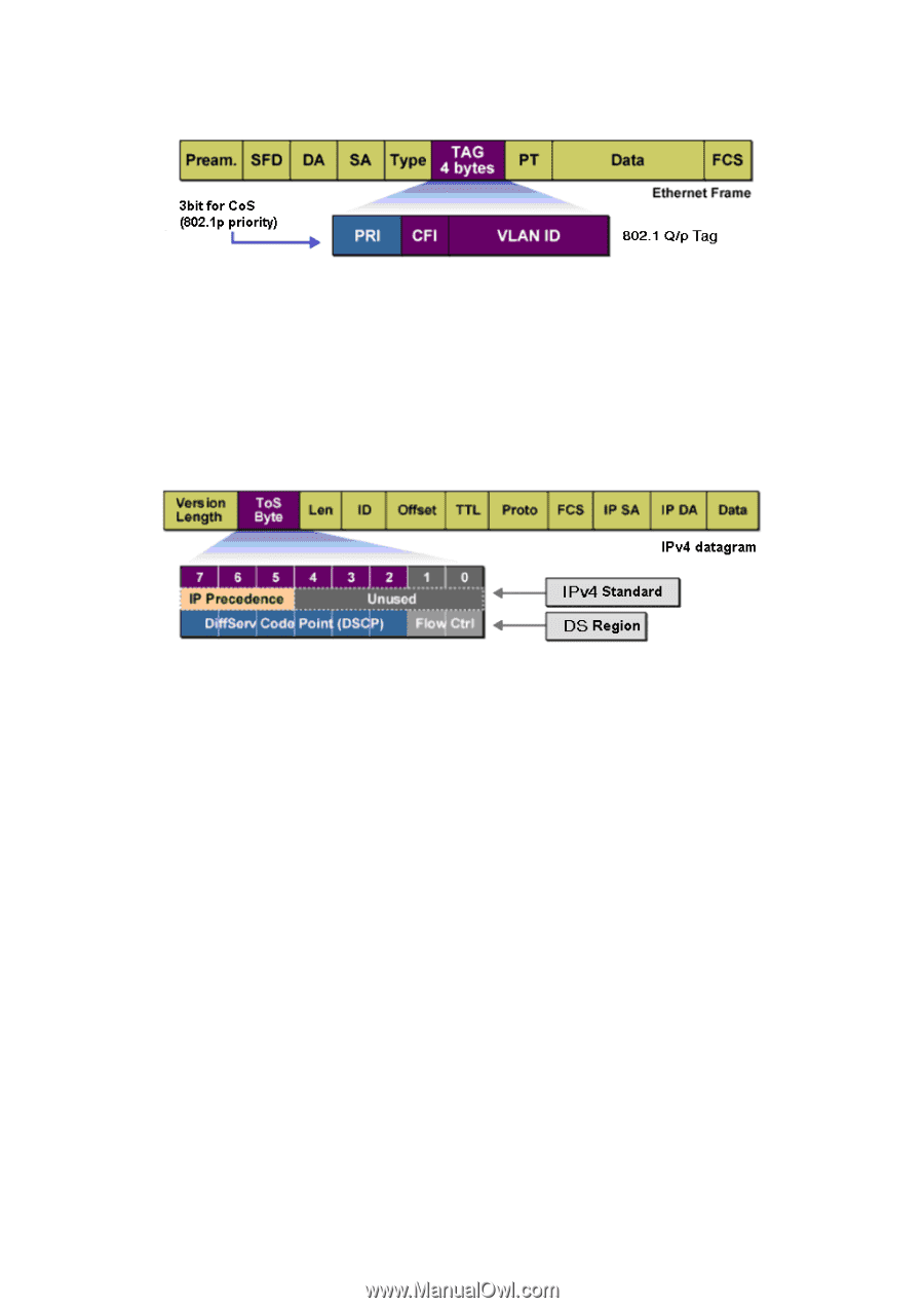
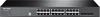
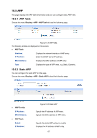
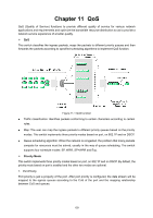
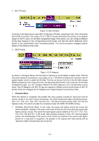
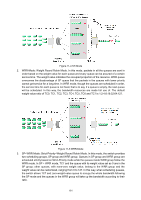
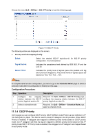
2. 802.1P Priority Figure 11-2 802.1Q frame As shown in the figure above, each 802.1Q Tag has a Pri field, comprising 3 bits. The 3-bit priority field is 802.1p priority in the range of 0 to 7. 802.1P priority determines the priority of the packets based on the Pri value. On the Web management page of the switch, you can configure different priority tags mapping to the corresponding priority levels, and then the switch determine which packet is sent preferentially when forwarding packets. The switch processes untagged packets based on the default priority mode. 3. DSCP Priority Figure 11-3 IP datagram As shown in the figure above, the ToS (Type of Service) in an IP header contains 8 bits. The first three bits indicate IP precedence in the range of 0 to 7. RFC2474 re-defines the ToS field in the IP packet header, which is called the DS field. The first six bits (bit 0-bit 5) of the DS field indicate DSCP precedence in the range of 0 to 63. The last 2 bits (bit 6 and bit 7) are reserved. On the Web management page, you can configure different DS field mapping to the corresponding priority levels. Non-IP datagram with 802.1Q tag are mapped to different priority levels based on 802.1P priority mode; the untagged non-IP datagram are mapped based on port priority mode. Schedule Mode When the network is congested, the problem that many packets compete for resources must be solved, usually in the way of queue scheduling. The switch implements eight scheduling queues, TC0, TC1, TC2, TC3, TC4, TC5, TC6 and TC7. TC0 has the lowest priority while TC7 has the highest priority. The switch provides four schedule modes: SP, WRR, SP+WRR and Equ. 1. SP-Mode: Strict-Priority Mode. In this mode, the queue with higher priority will occupy the whole bandwidth. Packets in the queue with lower priority are sent only when the queue with higher priority is empty. The switch has eight egress queues labeled as TC0, TC1, TC2, TC3, TC4, TC5, TC6 and TC7. In SP mode, their priorities increase in order. TC7 has the highest priority. The disadvantage of SP queue is that: if there are packets in the queues with higher priority for a long time in congestion, the packets in the queues with lower priority will be "starved to death" because they are not served. 160
-
 1
1 -
2
-
3
-
4
-
5
-
6
-
7
-
8
-
9
-
10
-
11
-
12
-
13
-
14
-
15
-
16
-
17
-
18
-
19
-
20
-
21
-
22
-
23
-
24
-
25
-
26
-
27
-
28
-
29
-
30
-
31
-
32
-
33
-
34
-
35
-
36
-
37
-
38
-
39
-
40
-
41
-
42
-
43
-
44
-
45
-
46
-
47
-
48
-
49
-
50
-
51
-
52
-
53
-
54
-
55
-
56
-
57
-
58
-
59
-
60
-
61
-
62
-
63
-
64
-
65
-
66
-
67
-
68
-
69
-
70
-
71
-
72
-
73
-
74
-
75
-
76
-
77
-
78
-
79
-
80
-
81
-
82
-
83
-
84
-
85
-
86
-
87
-
88
-
89
-
90
-
91
-
92
-
93
-
94
-
95
-
96
-
97
-
98
-
99
-
100
-
101
-
102
-
103
-
104
-
105
-
106
-
107
-
108
-
109
-
110
-
111
-
112
-
113
-
114
-
115
-
116
-
117
-
118
-
119
-
120
-
121
-
122
-
123
-
124
-
125
-
126
-
127
-
128
-
129
-
130
-
131
-
132
-
133
-
134
-
135
-
136
-
137
-
138
-
139
-
140
-
141
-
142
-
143
-
144
-
145
-
146
-
147
-
148
-
149
-
150
-
151
-
152
-
153
-
154
-
155
-
156
-
157
-
158
-
159
-
160
-
161
-
162
-
163
-
164
-
 165
165 -
 166
166 -
 167
167 -
 168
168 -
 169
169 -
 170
170 -
 171
171 -
 172
172 -
 173
173 -
 174
174 -
 175
175 -
176
-
177
-
178
-
179
-
180
-
181
-
182
-
183
-
184
-
185
-
186
-
187
-
188
-
189
-
190
-
191
-
192
-
193
-
194
-
195
-
196
-
197
-
198
-
199
-
200
-
201
-
202
-
203
-
204
-
205
-
206
-
207
-
208
-
209
-
210
-
211
-
212
-
213
-
214
-
215
-
216
-
217
-
218
-
219
-
220
-
221
-
222
-
223
-
224
-
225
-
226
-
227
-
228
-
229
-
230
-
231
-
232
-
233
-
234
-
235
-
236
-
237
-
238
-
239
-
240
-
241
-
242
-
243
-
244
-
245
-
246
-
247
-
248
-
249
-
250
-
251
-
252
-
253
-
254
-
255
-
256
-
257
-
258
-
259
-
260
-
261
-
262
-
263
-
264
-
265
-
266
-
267
-
268
-
269
-
270
-
271
-
272
-
273
-
274
-
275
-
276
-
277
-
278
-
279
-
280
-
281
-
282
-
283
-
284
-
285
 |
 |