TP-Link 10GE T1700G-28TQUN V1 User Guide - Page 21
System
 |
View all TP-Link 10GE manuals
Add to My Manuals
Save this manual to your list of manuals |
Page 21 highlights
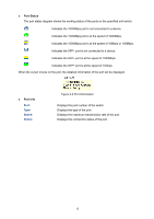
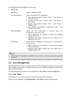
Chapter 4 System The System module is mainly for system configuration of the switch, including five submenus: System Info, User Management, System Tools, Access Security and SDM Template. 4.1 System Info The System Info, mainly for basic properties configuration, can be implemented on System Summary, Device Description, System Time and Daylight Saving Time pages. 4.1.1 System Summary On this page you can view the port connection status, the system information and the device information. The port status diagram shows the working status of 24 10/100/1000Mbps RJ45 ports and 4 SFP+ ports of the switch. Choose the menu System→System Info→System Summary to load the following page. Figure 4-1 System Summary 11
-
 1
1 -
2
-
3
-
4
-
5
-
6
-
7
-
8
-
9
-
10
-
11
-
12
-
13
-
14
-
15
-
 16
16 -
 17
17 -
 18
18 -
 19
19 -
 20
20 -
 21
21 -
 22
22 -
 23
23 -
 24
24 -
 25
25 -
 26
26 -
27
-
28
-
29
-
30
-
31
-
32
-
33
-
34
-
35
-
36
-
37
-
38
-
39
-
40
-
41
-
42
-
43
-
44
-
45
-
46
-
47
-
48
-
49
-
50
-
51
-
52
-
53
-
54
-
55
-
56
-
57
-
58
-
59
-
60
-
61
-
62
-
63
-
64
-
65
-
66
-
67
-
68
-
69
-
70
-
71
-
72
-
73
-
74
-
75
-
76
-
77
-
78
-
79
-
80
-
81
-
82
-
83
-
84
-
85
-
86
-
87
-
88
-
89
-
90
-
91
-
92
-
93
-
94
-
95
-
96
-
97
-
98
-
99
-
100
-
101
-
102
-
103
-
104
-
105
-
106
-
107
-
108
-
109
-
110
-
111
-
112
-
113
-
114
-
115
-
116
-
117
-
118
-
119
-
120
-
121
-
122
-
123
-
124
-
125
-
126
-
127
-
128
-
129
-
130
-
131
-
132
-
133
-
134
-
135
-
136
-
137
-
138
-
139
-
140
-
141
-
142
-
143
-
144
-
145
-
146
-
147
-
148
-
149
-
150
-
151
-
152
-
153
-
154
-
155
-
156
-
157
-
158
-
159
-
160
-
161
-
162
-
163
-
164
-
165
-
166
-
167
-
168
-
169
-
170
-
171
-
172
-
173
-
174
-
175
-
176
-
177
-
178
-
179
-
180
-
181
-
182
-
183
-
184
-
185
-
186
-
187
-
188
-
189
-
190
-
191
-
192
-
193
-
194
-
195
-
196
-
197
-
198
-
199
-
200
-
201
-
202
-
203
-
204
-
205
-
206
-
207
-
208
-
209
-
210
-
211
-
212
-
213
-
214
-
215
-
216
-
217
-
218
-
219
-
220
-
221
-
222
-
223
-
224
-
225
-
226
-
227
-
228
-
229
-
230
-
231
-
232
-
233
-
234
-
235
-
236
-
237
-
238
-
239
-
240
-
241
-
242
-
243
-
244
-
245
-
246
-
247
-
248
-
249
-
250
-
251
-
252
-
253
-
254
-
255
-
256
-
257
-
258
-
259
-
260
-
261
-
262
-
263
-
264
-
265
-
266
-
267
-
268
-
269
-
270
-
271
-
272
-
273
-
274
-
275
-
276
-
277
-
278
-
279
-
280
-
281
-
282
-
283
-
284
-
285
 |
 |
Chapter 4 System
The System module is mainly for system configuration of the switch, including five submenus:
System Info
,
User Management, System Tools
,
Access Security
and
SDM Template
.
4.1 System Info
The System Info, mainly for basic properties configuration, can be implemented on
System
Summary
,
Device Description
,
System Time
and
Daylight Saving Time
pages.
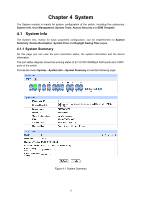
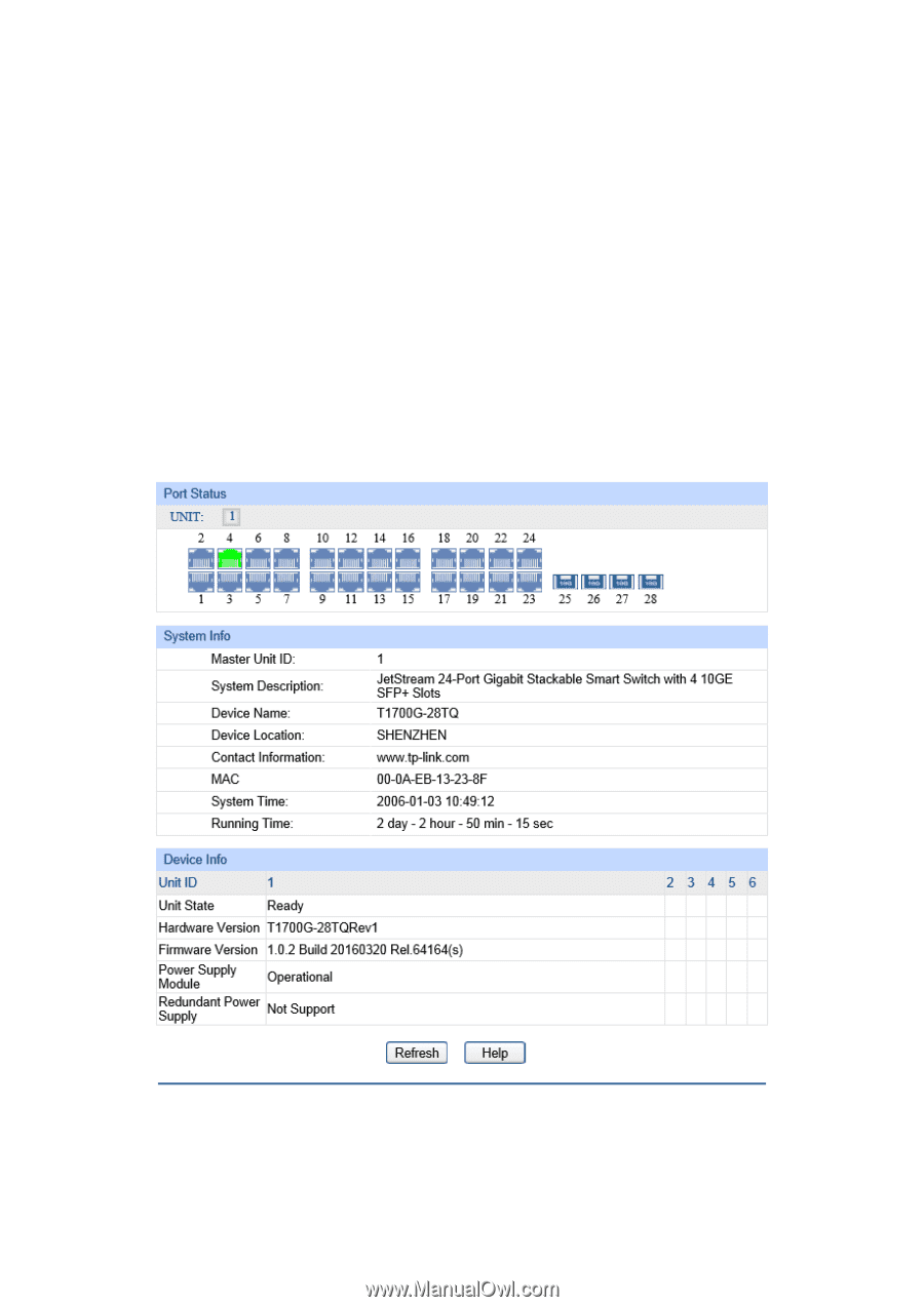
4.1.1 System Summary
On this page you can view the port connection status, the system information and the device
information.
The port status diagram shows the working status of 24 10/100/1000Mbps RJ45 ports and 4 SFP+
ports of the switch.
Choose the menu
System
→
System Info
→
System Summary
to load the following page.
Figure 4-1 System Summary
11