TP-Link 10GE T1700G-28TQUN V1 User Guide - Page 130
Querier Config
 |
View all TP-Link 10GE manuals
Add to My Manuals
Save this manual to your list of manuals |
Page 130 highlights
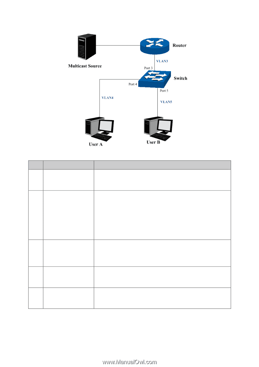
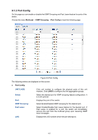
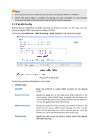
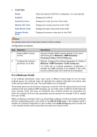
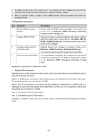
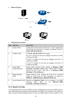
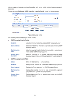
Network Diagram Configuration Procedure Step Operation Description 1 Create VLANs Create three VLANs with the VLAN ID 3, 4 and 5 respectively, and specify the description of VLAN3 as Multicast VLAN on VLAN→802.1Q VLAN page. 2 Configure ports On VLAN→802.1Q VLAN function pages. For port 3, configure its link type as Tagged, and add it to VLAN3, VLAN4 and VLAN5. For port 4, configure its link type as Untagged, and add it to VLAN3 and VLAN4. For port 5, configure its link type as Untagged, and add it to VLAN3 and VLAN5. 3 Enable IGMP snooping function Enable IGMP snooping function globally on Multicast→IGMP Snooping→Snooping Config page. Enable IGMP snooping function for port 3, port 4 and port 5 on Multicast→IGMP Snooping→Port Config page. 4 Enable Multicast VLAN Enable Multicast VLAN, configure the VLAN ID of a multicast VLAN as 3 and keep the other parameters as default on Multicast→IGMP Snooping→Multicast VLAN page. 5 Check Multicast VLAN Port 3-5 and Multicast VLAN 3 will be displayed in the IGMP snooping Status table on the Multicast→IGMP Snooping→Snooping Config page. 9.1.5 Querier Config In an IP multicast network that runs IGMP, a Layer 3 multicast device works as an IGMP querier to send IGMP queries and manage the multicast table. But IGMP is not supported by the devices in Layer 2 network. IGMP Snooping Querier can act as an IGMP Router in Layer 2 network. It can 120
-
 1
1 -
2
-
3
-
4
-
5
-
6
-
7
-
8
-
9
-
10
-
11
-
12
-
13
-
14
-
15
-
16
-
17
-
18
-
19
-
20
-
21
-
22
-
23
-
24
-
25
-
26
-
27
-
28
-
29
-
30
-
31
-
32
-
33
-
34
-
35
-
36
-
37
-
38
-
39
-
40
-
41
-
42
-
43
-
44
-
45
-
46
-
47
-
48
-
49
-
50
-
51
-
52
-
53
-
54
-
55
-
56
-
57
-
58
-
59
-
60
-
61
-
62
-
63
-
64
-
65
-
66
-
67
-
68
-
69
-
70
-
71
-
72
-
73
-
74
-
75
-
76
-
77
-
78
-
79
-
80
-
81
-
82
-
83
-
84
-
85
-
86
-
87
-
88
-
89
-
90
-
91
-
92
-
93
-
94
-
95
-
96
-
97
-
98
-
99
-
100
-
101
-
102
-
103
-
104
-
105
-
106
-
107
-
108
-
109
-
110
-
111
-
112
-
113
-
114
-
115
-
116
-
117
-
118
-
119
-
120
-
121
-
122
-
123
-
124
-
 125
125 -
 126
126 -
 127
127 -
 128
128 -
 129
129 -
 130
130 -
 131
131 -
 132
132 -
 133
133 -
 134
134 -
 135
135 -
136
-
137
-
138
-
139
-
140
-
141
-
142
-
143
-
144
-
145
-
146
-
147
-
148
-
149
-
150
-
151
-
152
-
153
-
154
-
155
-
156
-
157
-
158
-
159
-
160
-
161
-
162
-
163
-
164
-
165
-
166
-
167
-
168
-
169
-
170
-
171
-
172
-
173
-
174
-
175
-
176
-
177
-
178
-
179
-
180
-
181
-
182
-
183
-
184
-
185
-
186
-
187
-
188
-
189
-
190
-
191
-
192
-
193
-
194
-
195
-
196
-
197
-
198
-
199
-
200
-
201
-
202
-
203
-
204
-
205
-
206
-
207
-
208
-
209
-
210
-
211
-
212
-
213
-
214
-
215
-
216
-
217
-
218
-
219
-
220
-
221
-
222
-
223
-
224
-
225
-
226
-
227
-
228
-
229
-
230
-
231
-
232
-
233
-
234
-
235
-
236
-
237
-
238
-
239
-
240
-
241
-
242
-
243
-
244
-
245
-
246
-
247
-
248
-
249
-
250
-
251
-
252
-
253
-
254
-
255
-
256
-
257
-
258
-
259
-
260
-
261
-
262
-
263
-
264
-
265
-
266
-
267
-
268
-
269
-
270
-
271
-
272
-
273
-
274
-
275
-
276
-
277
-
278
-
279
-
280
-
281
-
282
-
283
-
284
-
285
 |
 |