ZyXEL GS1510-24 User Guide - Page 95
Spanning Tree Protocol
 |
View all ZyXEL GS1510-24 manuals
Add to My Manuals
Save this manual to your list of manuals |
Page 95 highlights
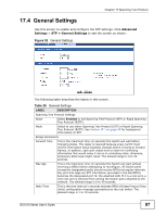
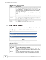
CHAPTER 17 Spanning Tree Protocol 17.1 Overview (R)STP detects and breaks network loops and provides backup links between switches, bridges or routers. It allows a Switch to interact with other (R)STPcompliant switches in your network to ensure that only one path exists between any two stations on the network. The Switch supports Spanning Tree Protocol (STP) and Rapid Spanning Tree Protocol (RSTP) as defined in the following standards. • IEEE 802.1D Spanning Tree Protocol • IEEE 802.1w Rapid Spanning Tree Protocol 17.2 What You Can DO • Use the General Settings screen (Section 17.4 on page 97) to enable and configure STP. • Use the STP Status screen (Section 17.5 on page 98) to check the STP current status. 17.3 What You Need to Know The Switch uses IEEE 802.1w RSTP (Rapid Spanning Tree Protocol) that allows faster convergence of the spanning tree than STP (while also being backwards compatible with STP-only aware bridges). In RSTP, topology change information is directly propagated throughout the network from the device that generates the topology change. In STP, a longer delay is required as the device that causes a topology change first notifies the root bridge and then the root bridge notifies the network. Both RSTP and STP flush unwanted learned addresses from the filtering database. In RSTP, the port states are Discarding, Learning, and Forwarding. Note: In this user's guide, "STP" refers to both STP and RSTP. GS1510 Series User's Guide 95
-
 1
1 -
2
-
3
-
4
-
5
-
6
-
7
-
8
-
9
-
10
-
11
-
12
-
13
-
14
-
15
-
16
-
17
-
18
-
19
-
20
-
21
-
22
-
23
-
24
-
25
-
26
-
27
-
28
-
29
-
30
-
31
-
32
-
33
-
34
-
35
-
36
-
37
-
38
-
39
-
40
-
41
-
42
-
43
-
44
-
45
-
46
-
47
-
48
-
49
-
50
-
51
-
52
-
53
-
54
-
55
-
56
-
57
-
58
-
59
-
60
-
61
-
62
-
63
-
64
-
65
-
66
-
67
-
68
-
69
-
70
-
71
-
72
-
73
-
74
-
75
-
76
-
77
-
78
-
79
-
80
-
81
-
82
-
83
-
84
-
85
-
86
-
87
-
88
-
89
-
 90
90 -
 91
91 -
 92
92 -
 93
93 -
 94
94 -
 95
95 -
 96
96 -
 97
97 -
 98
98 -
 99
99 -
 100
100 -
101
-
102
-
103
-
104
-
105
-
106
-
107
-
108
-
109
-
110
-
111
-
112
-
113
-
114
-
115
-
116
-
117
-
118
-
119
-
120
-
121
-
122
-
123
-
124
-
125
-
126
-
127
-
128
-
129
-
130
-
131
-
132
-
133
-
134
-
135
-
136
-
137
-
138
-
139
-
140
-
141
-
142
-
143
-
144
-
145
-
146
-
147
-
148
-
149
-
150
-
151
-
152
-
153
-
154
-
155
-
156
-
157
-
158
-
159
-
160
-
161
-
162
-
163
-
164
-
165
-
166
-
167
-
168
-
169
-
170
-
171
-
172
-
173
-
174
-
175
-
176
-
177
-
178
-
179
-
180
-
181
-
182
-
183
-
184
-
185
-
186
-
187
-
188
-
189
-
190
-
191
-
192
-
193
-
194
-
195
-
196
-
197
-
198
-
199
-
200
-
201
-
202
-
203
-
204
 |
 |