Brother International DCP-1400 Service Manual - Page 105
voltage, Power, Supply, Inlet
 |
View all Brother International DCP-1400 manuals
Add to My Manuals
Save this manual to your list of manuals |
Page 105 highlights
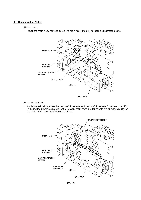
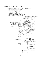
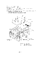
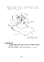
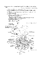
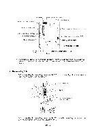
1.23 Low-voltage Power Supply PCB and Power Inlet (1) Remove two screws "g" and take off the rear underbar. (2) Remove screw "h." (3) Slightly lift up the low-voltage power supply PCB and disconnect the heater harness and mainLV-engine harness. The low-voltage power supply PCB is connected to the power inlet with soldered lead wires. (4) Remove screw "i." (5) While holding up the low-voltage power supply PCB, take out the power inlet from the main chassis to the inside in the direction of the arrow shown below. (6) To separate the power inlet from the low-voltage power supply PCB, unsolder the two lead wires from the PCB. g Low-voltage power supply PCB "h" "g" Rear underbar „.7 (Front underbar) O Power inlet Main chassis placed upside down Main-LV-engine harness Cutout "X" provided in the support film Heater harness (Rear) Power inlet Grounding wire "g" and "i": Taptite, cup S M3x6 "h": Taptite, cup S M3x6 0 (Tightening torque: 0.5 N•m) Cutout "Y" provided in the support film Routing the grounding wire IV - 61
-
 1
1 -
2
-
3
-
4
-
5
-
6
-
7
-
8
-
9
-
10
-
11
-
12
-
13
-
14
-
15
-
16
-
17
-
18
-
19
-
20
-
21
-
22
-
23
-
24
-
25
-
26
-
27
-
28
-
29
-
30
-
31
-
32
-
33
-
34
-
35
-
36
-
37
-
38
-
39
-
40
-
41
-
42
-
43
-
44
-
45
-
46
-
47
-
48
-
49
-
50
-
51
-
52
-
53
-
54
-
55
-
56
-
57
-
58
-
59
-
60
-
61
-
62
-
63
-
64
-
65
-
66
-
67
-
68
-
69
-
70
-
71
-
72
-
73
-
74
-
75
-
76
-
77
-
78
-
79
-
80
-
81
-
82
-
83
-
84
-
85
-
86
-
87
-
88
-
89
-
90
-
91
-
92
-
93
-
94
-
95
-
96
-
97
-
98
-
99
-
 100
100 -
 101
101 -
 102
102 -
 103
103 -
 104
104 -
 105
105 -
 106
106 -
 107
107 -
 108
108 -
 109
109 -
 110
110 -
111
-
112
-
113
-
114
-
115
-
116
-
117
-
118
-
119
-
120
-
121
-
122
-
123
-
124
-
125
-
126
-
127
-
128
-
129
-
130
-
131
-
132
-
133
-
134
-
135
-
136
-
137
-
138
-
139
-
140
-
141
-
142
-
143
-
144
-
145
-
146
-
147
-
148
-
149
-
150
-
151
-
152
-
153
-
154
-
155
-
156
-
157
-
158
-
159
-
160
-
161
-
162
-
163
-
164
-
165
-
166
-
167
-
168
-
169
-
170
-
171
-
172
-
173
-
174
-
175
-
176
-
177
-
178
-
179
-
180
-
181
-
182
-
183
-
184
-
185
-
186
-
187
-
188
-
189
-
190
-
191
-
192
-
193
-
194
-
195
-
196
-
197
-
198
-
199
-
200
-
201
-
202
-
203
-
204
-
205
-
206
-
207
-
208
-
209
-
210
-
211
-
212
-
213
-
214
-
215
-
216
-
217
-
218
-
219
-
220
-
221
-
222
-
223
-
224
-
225
-
226
-
227
-
228
-
229
 |
 |
