Brother International DCP-1400 Service Manual - Page 64
disconnect
 |
View all Brother International DCP-1400 manuals
Add to My Manuals
Save this manual to your list of manuals |
Page 64 highlights
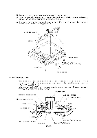
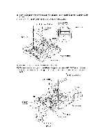
3) Turn the gear 17/97 to move the CCD unit to the right to make the following job easier. 4) Remove screw "a" and take out the CCD rail clamp. (See the illustration given on the next page.) 5) Remove two screws "b" from the CCD idle pulley holder, then remove the CCD drive belt from the idle pulley. 6) Lift up the CCD rail together with the CCD unit and CCD drive belt, and then disconnect the CCD flat cable. NOTE: When handling the CCD unit, do not touch the CCD PCB or glasses but hold the hatched sections as shown below. These hatched sections are allowed to touch. V' o O0 0 =O _r CCD PCB 7) Pull out the CCD rail from the CCD unit. 8) Remove the CCD lock. CCD unit Pressure spring CCD rail Spring II II CCD idle pulley holder 6 CCD unit CCD drive belt "a": Taptite, cup B M3x8 "b": Taptite, pan B M3x10 "a" Gear 17/97 0 CCD rail 0 clamp CCD lock CCD flat cable IV - 20 Scanner base (Front) Panel harness
-
 1
1 -
2
-
3
-
4
-
5
-
6
-
7
-
8
-
9
-
10
-
11
-
12
-
13
-
14
-
15
-
16
-
17
-
18
-
19
-
20
-
21
-
22
-
23
-
24
-
25
-
26
-
27
-
28
-
29
-
30
-
31
-
32
-
33
-
34
-
35
-
36
-
37
-
38
-
39
-
40
-
41
-
42
-
43
-
44
-
45
-
46
-
47
-
48
-
49
-
50
-
51
-
52
-
53
-
54
-
55
-
56
-
57
-
58
-
 59
59 -
 60
60 -
 61
61 -
 62
62 -
 63
63 -
 64
64 -
 65
65 -
 66
66 -
 67
67 -
 68
68 -
 69
69 -
70
-
71
-
72
-
73
-
74
-
75
-
76
-
77
-
78
-
79
-
80
-
81
-
82
-
83
-
84
-
85
-
86
-
87
-
88
-
89
-
90
-
91
-
92
-
93
-
94
-
95
-
96
-
97
-
98
-
99
-
100
-
101
-
102
-
103
-
104
-
105
-
106
-
107
-
108
-
109
-
110
-
111
-
112
-
113
-
114
-
115
-
116
-
117
-
118
-
119
-
120
-
121
-
122
-
123
-
124
-
125
-
126
-
127
-
128
-
129
-
130
-
131
-
132
-
133
-
134
-
135
-
136
-
137
-
138
-
139
-
140
-
141
-
142
-
143
-
144
-
145
-
146
-
147
-
148
-
149
-
150
-
151
-
152
-
153
-
154
-
155
-
156
-
157
-
158
-
159
-
160
-
161
-
162
-
163
-
164
-
165
-
166
-
167
-
168
-
169
-
170
-
171
-
172
-
173
-
174
-
175
-
176
-
177
-
178
-
179
-
180
-
181
-
182
-
183
-
184
-
185
-
186
-
187
-
188
-
189
-
190
-
191
-
192
-
193
-
194
-
195
-
196
-
197
-
198
-
199
-
200
-
201
-
202
-
203
-
204
-
205
-
206
-
207
-
208
-
209
-
210
-
211
-
212
-
213
-
214
-
215
-
216
-
217
-
218
-
219
-
220
-
221
-
222
-
223
-
224
-
225
-
226
-
227
-
228
-
229
 |
 |
