Brother International DCP-1400 Service Manual - Page 88
Pressure, roller, Lower, frame, cleaner, spring, bushing, Thermistor, Cleaner, pinch, placed,
 |
View all Brother International DCP-1400 manuals
Add to My Manuals
Save this manual to your list of manuals |
Page 88 highlights
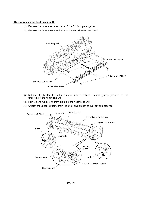
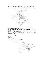
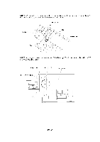
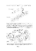
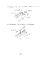
(12) From the lower FU frame, gently lift up the right end of the pressure roller 25 and remove it. Pressure roller 25 c) g, Lower FU frame (13) At each of the right and left ends of the lower FU frame, push down the PR bushing to incline it inwards and take it out. Remove the PR springs also. (14) At each of the four aligned cleaner pinch rollers, pinch section "A" of the claw cleaner spring and pull it up and out of the lower FU frame. Then remove those four cleaner pinch rollers. (15) At the cleaner pinch roller placed inwards, pinch section "B" of the thermistor cleaner spring and pull it up and out of the lower FU frame. Lower FU frame Claw cleaner spring 1.....-% fi r, Thermistor PR bushing Cleaner pinch roller cleaner spring (placed inwards) Cleaner pinch rollers (aligned) 1 . (,) PR spring C\ '(I c%) PR bushing PR spring "B" NOTE: When setting claw cleaner springs and thermistor cleaner spring into the lower FU frame, fully push them in so that sections A and B will not protrude from the frame. IV - 44
-
 1
1 -
2
-
3
-
4
-
5
-
6
-
7
-
8
-
9
-
10
-
11
-
12
-
13
-
14
-
15
-
16
-
17
-
18
-
19
-
20
-
21
-
22
-
23
-
24
-
25
-
26
-
27
-
28
-
29
-
30
-
31
-
32
-
33
-
34
-
35
-
36
-
37
-
38
-
39
-
40
-
41
-
42
-
43
-
44
-
45
-
46
-
47
-
48
-
49
-
50
-
51
-
52
-
53
-
54
-
55
-
56
-
57
-
58
-
59
-
60
-
61
-
62
-
63
-
64
-
65
-
66
-
67
-
68
-
69
-
70
-
71
-
72
-
73
-
74
-
75
-
76
-
77
-
78
-
79
-
80
-
81
-
82
-
 83
83 -
 84
84 -
 85
85 -
 86
86 -
 87
87 -
 88
88 -
 89
89 -
 90
90 -
 91
91 -
 92
92 -
 93
93 -
94
-
95
-
96
-
97
-
98
-
99
-
100
-
101
-
102
-
103
-
104
-
105
-
106
-
107
-
108
-
109
-
110
-
111
-
112
-
113
-
114
-
115
-
116
-
117
-
118
-
119
-
120
-
121
-
122
-
123
-
124
-
125
-
126
-
127
-
128
-
129
-
130
-
131
-
132
-
133
-
134
-
135
-
136
-
137
-
138
-
139
-
140
-
141
-
142
-
143
-
144
-
145
-
146
-
147
-
148
-
149
-
150
-
151
-
152
-
153
-
154
-
155
-
156
-
157
-
158
-
159
-
160
-
161
-
162
-
163
-
164
-
165
-
166
-
167
-
168
-
169
-
170
-
171
-
172
-
173
-
174
-
175
-
176
-
177
-
178
-
179
-
180
-
181
-
182
-
183
-
184
-
185
-
186
-
187
-
188
-
189
-
190
-
191
-
192
-
193
-
194
-
195
-
196
-
197
-
198
-
199
-
200
-
201
-
202
-
203
-
204
-
205
-
206
-
207
-
208
-
209
-
210
-
211
-
212
-
213
-
214
-
215
-
216
-
217
-
218
-
219
-
220
-
221
-
222
-
223
-
224
-
225
-
226
-
227
-
228
-
229
 |
 |
