Brother International DCP-1400 Service Manual - Page 62
M3x10
 |
View all Brother International DCP-1400 manuals
Add to My Manuals
Save this manual to your list of manuals |
Page 62 highlights
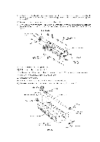
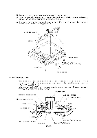
(3) Remove the three screws from the underside of the scanner base. (4) Insert the tip of a flat screwdriver into each of the four holes provided in the scanner base and unhook the four latches while lifting up the control panel ASSY. (5) Disconnect the panel harness from the control panel PCB. (For the disassembly procedure of the control panel ASSY, refer to page IV-24.) Control panel ASSY Latches / S I\ \ I \ \ '\. 0 Panel harness •. I 6 Scanner base a Taptite, cup B M3x10 (Tightening torque: 0.69 NI•m) I4 ii Flat screwdriver • Reassembling Notes • When reinstalling the scanner unit, fit the holes and cutouts provided in the scanner unit over screws "A" and pawls of the scanner mount, respectively, and then slide the scanner unit to the front. (Refer to page IV-17.) • When connecting the CCD motor harness, panel harness, and scanner HP sensor harness to the relay PCB, route them as shown below. CCD flat cable Scanner HP sensor harness Document sensor harness II I IIIIIIIIIL_ ADF motor harness CCD motor harness Panel harness L ' 11 Speaker harness ..\•P ,-,11 Main-relay (panel) harness Relay PCB IV - 18 Main-relay (motors) harness Main-relay (CCD) harness
-
 1
1 -
2
-
3
-
4
-
5
-
6
-
7
-
8
-
9
-
10
-
11
-
12
-
13
-
14
-
15
-
16
-
17
-
18
-
19
-
20
-
21
-
22
-
23
-
24
-
25
-
26
-
27
-
28
-
29
-
30
-
31
-
32
-
33
-
34
-
35
-
36
-
37
-
38
-
39
-
40
-
41
-
42
-
43
-
44
-
45
-
46
-
47
-
48
-
49
-
50
-
51
-
52
-
53
-
54
-
55
-
56
-
 57
57 -
 58
58 -
 59
59 -
 60
60 -
 61
61 -
 62
62 -
 63
63 -
 64
64 -
 65
65 -
 66
66 -
 67
67 -
68
-
69
-
70
-
71
-
72
-
73
-
74
-
75
-
76
-
77
-
78
-
79
-
80
-
81
-
82
-
83
-
84
-
85
-
86
-
87
-
88
-
89
-
90
-
91
-
92
-
93
-
94
-
95
-
96
-
97
-
98
-
99
-
100
-
101
-
102
-
103
-
104
-
105
-
106
-
107
-
108
-
109
-
110
-
111
-
112
-
113
-
114
-
115
-
116
-
117
-
118
-
119
-
120
-
121
-
122
-
123
-
124
-
125
-
126
-
127
-
128
-
129
-
130
-
131
-
132
-
133
-
134
-
135
-
136
-
137
-
138
-
139
-
140
-
141
-
142
-
143
-
144
-
145
-
146
-
147
-
148
-
149
-
150
-
151
-
152
-
153
-
154
-
155
-
156
-
157
-
158
-
159
-
160
-
161
-
162
-
163
-
164
-
165
-
166
-
167
-
168
-
169
-
170
-
171
-
172
-
173
-
174
-
175
-
176
-
177
-
178
-
179
-
180
-
181
-
182
-
183
-
184
-
185
-
186
-
187
-
188
-
189
-
190
-
191
-
192
-
193
-
194
-
195
-
196
-
197
-
198
-
199
-
200
-
201
-
202
-
203
-
204
-
205
-
206
-
207
-
208
-
209
-
210
-
211
-
212
-
213
-
214
-
215
-
216
-
217
-
218
-
219
-
220
-
221
-
222
-
223
-
224
-
225
-
226
-
227
-
228
-
229
 |
 |
